Data Sheets
53
At inputs: Load of the signal
4 F = 8 mA at 24 V
signal range: +13...+33 V
At outputs: Loadability of the signal
100 F = 200 mA
Loadability of the output ≤ 15 W
Positive pole of the 24 VDC supply voltage
Reference pole of the 24 VDC supply voltage
Positive pole of the microprocessor system
Reference pole of the microprocessor system
10.13.5 Color Code for Lead Marking in Accordance to DIN IEC 60757
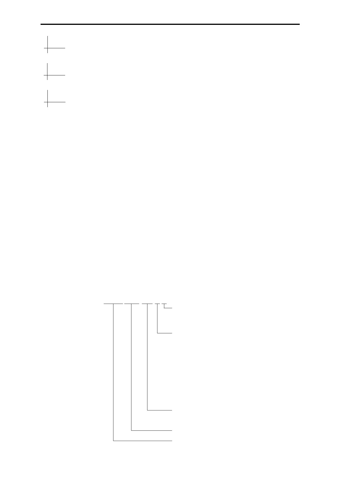
10.13.6 Description of the Order Code for Cable Plugs
Standard cable plugs: see HIMA price list
BK black VT violet
BN brown GY gray
RD red WH white
OG orange PK pink
YE yellow GD gold
GN green TQ turquoise
BU blue SR silver
4 F
100 F
≤ 15 W
L+
L-
+5 V
GND
R1 = plug 1 redundant inputs
R2 = plug 2 redundant inputs
S = (order includes drawing,
special design)
I = 0/4...20mA active transmitter
IT = 0/4...20 mA passive transmitter
ITI = 0/4...20mA active & passive transmitter
U60mV = 0...60 mV
U1V = 0...1V
U5V = 0...5 V
U10V = 0...10 V
2P = Pt 100 two-wire technique
3P = Pt 100 three-wire technique
U>65V = voltage >65 V
and single wires
P2 = 2-pole connection
C = cable LiYY or LIYCY, nn = length in m
W = single cores, nn = length in m
ExW = single cores blue Ex, nn = length in m
ExC = cable with blue cover Ex,
nn = length in m
number of the according F module
24P2 = 2-pole connection 24 VDC
48P2 = 2-pole connection 48 VDC
Z7nnn
nnnn
nnn
A
B