H 7014 (0507)
474
The channels are individually checked for short-circuit or overload current and switched off if
necessary. Resetting the fuses is made via a common reset input (W) for 24 VDC or via the
internal reset pushbutton.
The fuses can be tripped together via an input (T) for a 24 VDC signal or individually with own
test pushbuttons. The fuse trip is indicated with LEDs and signalized via a common output (F).
If this output is not used, it must be terminated against L- with a resistor of 10 k
Ω (0.25 W).
Connections and cross sections
T, F, W 1 female plug-in connection 1.5 mm
2
, 3-pole
IN 1 female plug-in connection 1.5 mm
2
, 9-pole
OUT Screw terminals for loads 2.5 mm
2
, 2 x 8-pole
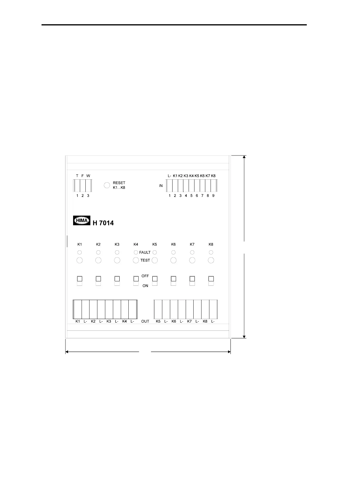
Mechanical design and dimensions
Figure 2: Mechanical design and dimensions
Depth 57 mm (with terminals)
Mounting on DIN rail 35 mm
Mounting position horizontal or vertical
Assembling distance not required
1
12
 Loading...