B 5233-1/-2 / H51q-HS/HRS (0605)
127
4.3 Connection of the monitoring loop (for fuses and fans)
4.4 Internal fuses
4.5 I/O bus
The data connection of the I/O level with the central module is established via the I/O bus.
4.5.1 System H51q-HS
The data cable BV 7032 connects the I/O buses of central module 1 (XD.2) to central module
2 (XD.1).
I/O bus, H51q-HS / B 5233-1
4.5.2 System H51q-HRS
The system H 51q-HRS has a redundant I/O bus. Each of the central modules has its own I/O
bus and therefore only the correlated I/O subracks. The 1st I/O bus is assigned to central mod-
ule 1 and the 2nd I/O bus is assigned to central module 2.
I/O bus, H51q-HRS/ B 5233-2
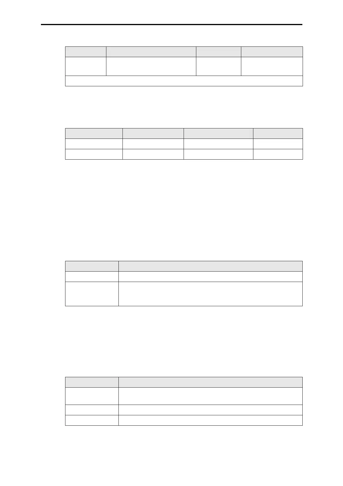
Connection Wire and connection Fusing Use
XG.26:4/5/6
GY 0.5 mm
2
, Faston 2.8 x 0.8
max. 4 A slow
blow
Floating NO/NC con-
tact for signaling
GY = Color code gray
Table 5: Connection of the monitoring loop
Position Size Dimension HIMA part no.
Z 6011 4 A slow blow 5 x 20 mm 57 0174409
Z 6013 1.6 A slow blow 5 x 20 mm 57 0174169
Table 6: Internal fuses
Connection Procedure
XD.1 to XD.2 Connect with cable BV 7032
XD.4 Remove bus termination module F 7546 and plug it on XD.2 of the last
I/O rack, then connect cable BV 7032 from XD.1 of the 1st I/O rack to
empty terminal XD.4
Table 7: I/O bus, H51q-HS / B 5233-1
Connection Procedure
XD.3 and XD.4 Remove bus termination module F 7546 and plug it on XD.2 of the last
I/O rack of both I/O buses
XD.4 Plug in cable BV 7032 of the 1st I/O rack to the 1st I/O bus
XD.3 Plug in cable BV 7032 of the 2nd I/O rack to the 2nd I/O bus
Table 8: I/O bus, H51q-HRS / B 5233-2
 Loading...