BV 7043 (0508)
156
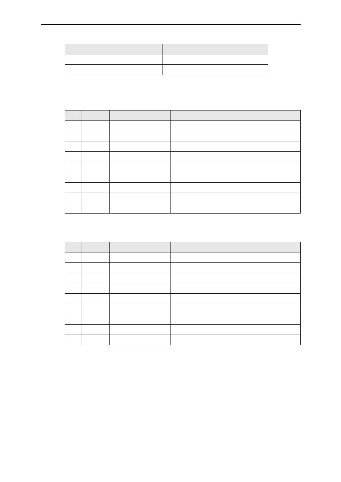
Table 1: Maximum cable length depending on transmission rate
Table 2: Pin assignment of the interface RS 485, 9-pole
Table 3: Pin assignment of the interface RS 232, 9-pole
Transmission rate Maximum cable length
9 600 bps 15 m
57 600 bps 5 m
Pin RS 485 Signal Meaning
1 - - not used
2 - RP 5 V, decoupled by diodes
3 A/A’ RxD/TxD-A Receive/Transmit Data A
4 - CNTR-A Control signal A
5 C/C’ DGND Data Ground
6 - VP 5 V, positive pole of power supply
7 - - not used
8 B/B’ RxD/TxD-B Receive/Transmit Data B
9 - CNTR-B Control signal B
Pin RS 232 Signal Meaning
1 CF DCD Data could be received
2 BB RxD Receive data from interface to PC
3 BA TxD Send data from PC to interface
4 CD DTR PC ready to receive
5 AB GND Data Ground
6 CC DSR Interface ready to receive
7 A RTS PC indicates that PC would send
8 CF CTS Interface indicates that PC could send
9 CE RI Ring indicator
 Loading...