BV 7048 (0508)
164
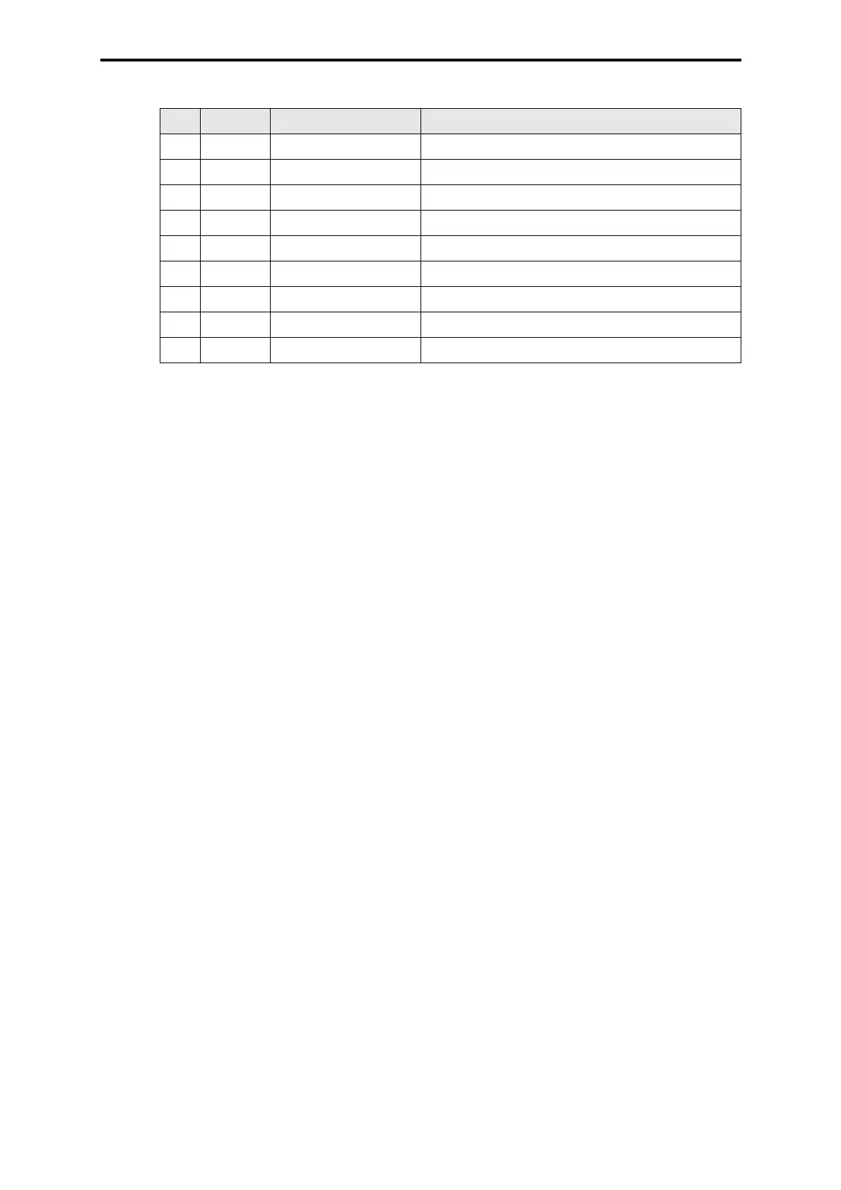
Table 1: Pin assignment of the interface RS 485, 9-pole
Pin RS 485 Signal Meaning
1 - - not used
2 - RP 5 V, decoupled by diodes
3 A/A’ RxD/TxD-A Receive/Transmit Data A
4 - CNTR-A Control signal A
5 C/C’ DGND Data Ground
6 - VP 5 V, positive pole of power supply
7 - - not used
8 B/B’ RxD/TxD-B Receive/Transmit Data B
9 - CNTR-B Control signal B
 Loading...