F 3237 (0622)
198
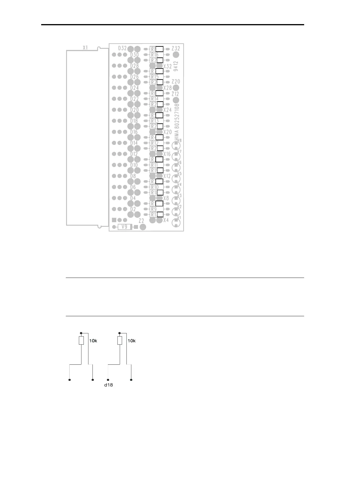
Figure 5: Cable connector Z 7108 (special design for NAMUR)
Termination of not used inputs
Figure 6: Resistor circuit for the inputs
Note Not used inputs, which are connected in the HIMA function block HB-
RTE-3, must be terminated with a 10 k
Ω resistor at the input of the
module. Thereby line error messages of the not used input channels
are eliminated (see following scheme).
Resistors R*:
R17-R24: 681
Ω
Resistors R**:
R1-R8: 390
Ω
R*
R*
R*
R*
R**
R*
R**
R**
R*
R**
R*
R*
R**
R**
R**
R**
d2
d4
d20
channel 1
channel 5
Example:
Channel 1 and channel 5 are not used.
Termination of channel 1 (connections d2-d4) and
channel 5 (connections d18-d20) each with 10 k
Ω.