F 3238 (0622)
200
The module is tested completely during operation.
The main test routines are:
• Switch-on and switch-off capability
• Crosstalk on the input circuits by walking-zero
• Functions of the input filters
• Correct function of the module
• Short circuit and wire break of the sensor line
The LEDs are not tested.
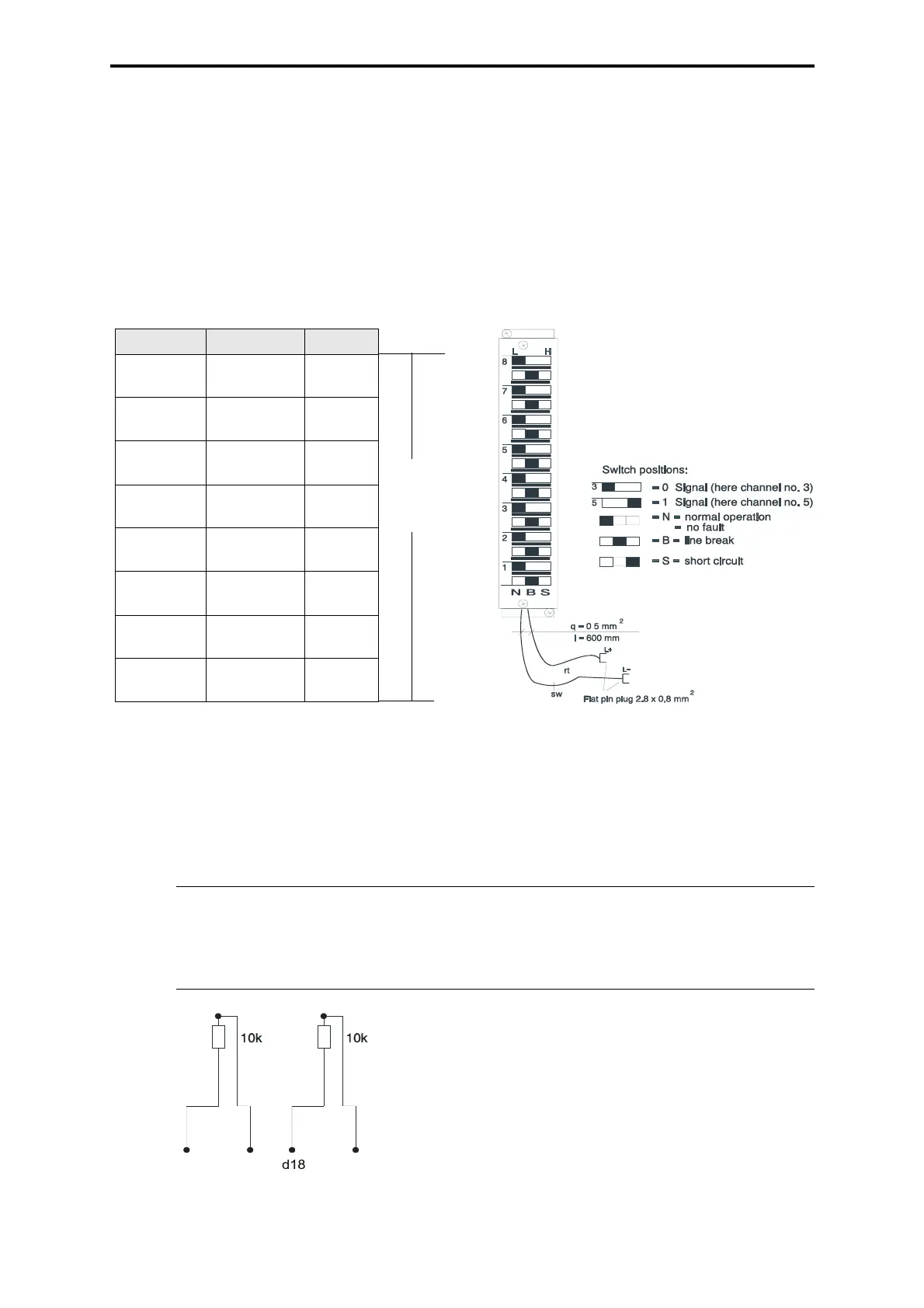
Figure 2: Connection wiring
* The connections (X4) to (X32) are only used at special cable connectors.
Termination of not used inputs
Figure 3: Resistor circuit for the inputs
Note Not used inputs, which are connected in the HIMA function block HB-
RTE-3, must be terminated with a 10 k
Ω resistor at the input of the
module. Thereby line error messages of the not used input channels
are eliminated (see following scheme).
Channel Connection Color
1d2
d4 (x4)*
WH
BN
2d6
d8 (x8)*
GN
YE
3 d10
d12 (x12)*
GY
PK
4 d14
d16 (x16)*
BU
RD
5 d18
d20 (x20)*
BK
VT
6 d22
d24 (x24)*
WHBN
WHGN
7 d26
d28 (x28)*
WHYE
WHGY
8 d30
d32 (x32)*
WHPK
WHBU
Assembly cable plug Z 7204
.
Cable
LiYY
16 x 0.5 mm
2
Lead marking cable plug
Z 7008 / 3238 / C.. gray or
Z 7008 / 3238 / ExC.. blue
d2
d4
d2
channel 1
channel 5
Example:
Channel 1 and channel 5 are not used.
Termination of channel 1 (connections d2-d4) and
channel 5 (connections d18-d20) each with 10 k
Ω.
 Loading...