F 3238 (0622)
203
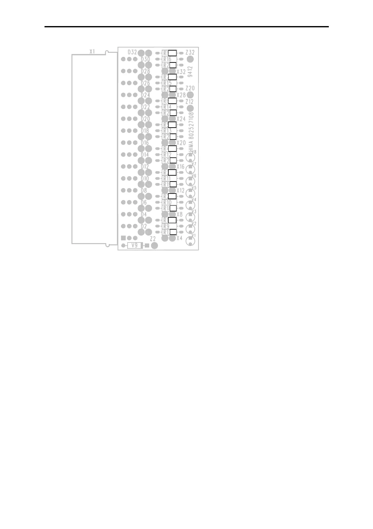
Figure 6: Cable connector Z 7008 (special design for NAMUR)
1.6 Installation
• The electronic module including its connections has to be installed in a way that at least
the system of protection IP 20 according to EN 60529: 1991 + A1: 2000 is achieved.
• If two intrinsically safe input circuits of two F 3238 modules are wired in parallel, a spe-
cial cable provided by HIMA, must be used.
• The separation between intrinsically safe and not intrinsically safe terminals must be
≥ 50 mm, especially between adjacent modules.
• The separation between adjacent intrinsically safe terminals must be
≥ 6 mm.
• Intrinsically safe and not intrinsically safe lines must be installed separately, or the
intrinsically safe lines must be provided with additional insulation.
• Intrinsically safe lines must be identifiable, e.g. by a light blue color (RAL 5015) of the
insulation.
• The wiring has to be secured mechanically in a way which ensures that in the event of
an accidental disconnection, the distance (EN 50 020/ Part 7, Table 4) between the
intrinsically safe and not intrinsically safe connections does not fall below the required
minimum (e.g. by bundling).
The cables/ wires used must comply with the following dielectric withstand test:
• Intrinsically safe lines
≥ 1000 VAC
• Not intrinsically safe lines
≥ 1500 VAC
For stranded wires, suitable measures must be applied to prevent spreading at the end of wire.
The terminals must be suitable for clamping the wire cross section.
Resistors R*:
R17-R24: 681
Ω
Resistors R**:
R1-R8: 390
Ω
R*
R*
R*
R*
R**
R*
R**
R**
R*
R**
R*
R*
R**
R**
R**
R**
 Loading...