F 3332 (0524)
234
Figure 2: Lead markings of the cable plugs
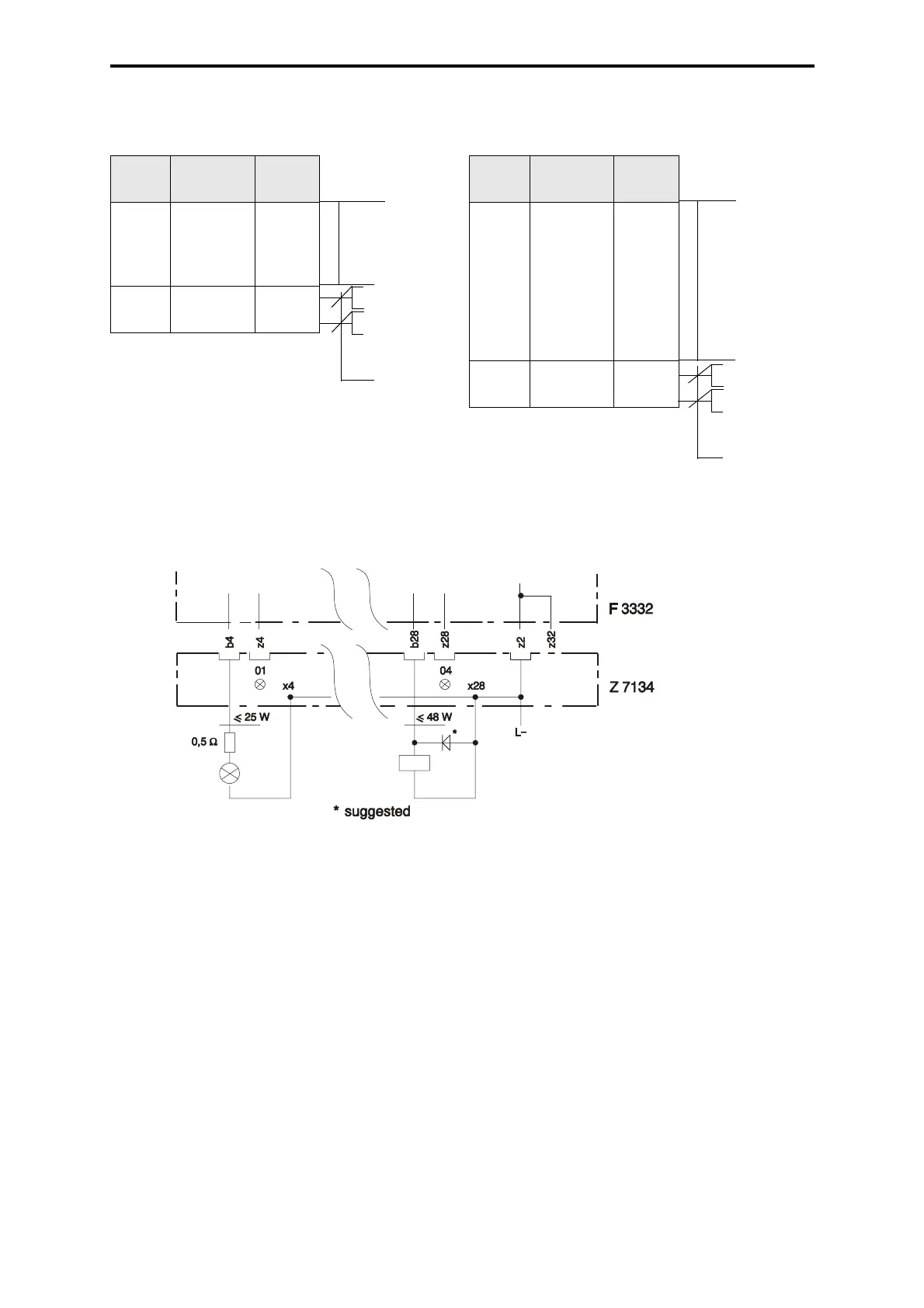
Figure 3: 2-pole connection
Planning notes
– at the same time only 2 channels may be operated with the max. load (2 A). If the load is
up to max. 1 A, all channels may be operated at the same time.
– max. 10 output modules with nominal load may be used in one I/O subrack
– can be used in parallel without external diodes
Lead marking of the cable plug
Z 7134 / 3332 / C.. / P2
(2-pole connection)
Chan-
nel
Connec-
tion
Color
1
2
3
4
b4
x4
b8
x8
b24
x24
b28
x28
BN
WH
YE
GN
PK
GY
RD
BU
L–
L+
z2
z12
BK
RD
Cable
LiYY 8 x
1.5 mm
2
Flat pin
plug
2.8 x
0.8 mm
2
q = 1 mm
2
l = 750 mm
Lead marking of the cable plug
Z 7134 / 3332 / C..
Chan-
nel
Connec-
tion
Color
1
2
3
4
b4
b8
b24
b28
WH
BN
GN
YE
L–
L+
z2
z12
BK
RD
Flat pin
plug
2.8 x
0.8 mm
2
q = 1 mm
2
l = 750 mm
Cable
LiYY 4 x
1.5 mm
2
 Loading...