F 6215 (0507)
281
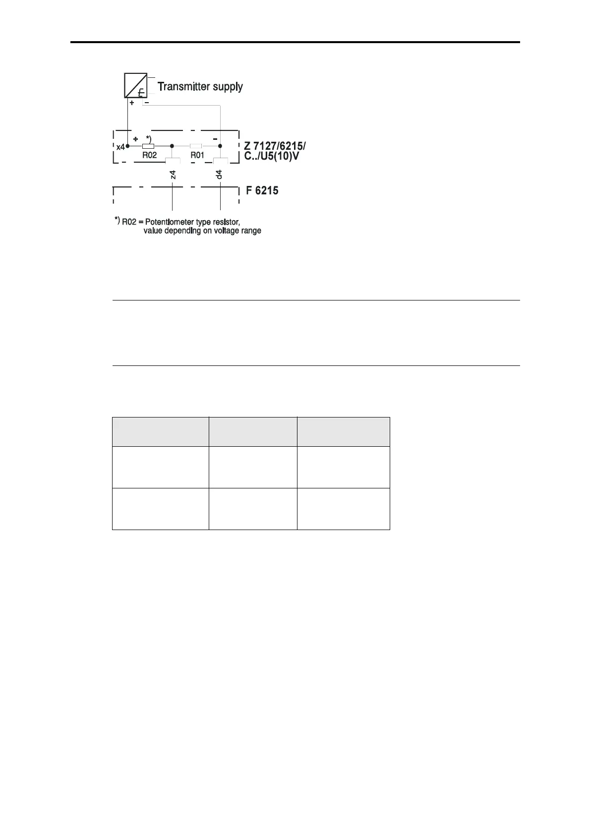
Figure 3: Connection with potentiometer (for voltage areas ≠ 0...1 V)
Note to the connection with potentiometer:
Resistor equipment for the potentiometers on Z 7127 / 6215,
channel 1...8:
Note
Due to the tolerance of the potentiometer resistors the accuracy
defined in the data sheet is at first guaranteed after a new balancing of
all channels within the user program, or resistors with tolerances < 1 %
have to be used.
Measuring range
U
M
R01, 03, 05, 07,
09, 11, 13, 15
R02, 04, 06, 08
10, 12, 14, 16
U
M
= 0...5 V
Value
Part no.
33.2 k
Ω, 1%
00 0751333
133 kΩ, 1%
00 0751134
U
M
= 0...10 V
Value
Part no.
20 k
Ω, 1%
00 0751203
178 kΩ, 1%
00 0751174
Table 1: Resistor equipment