F 6217 (0606)
292
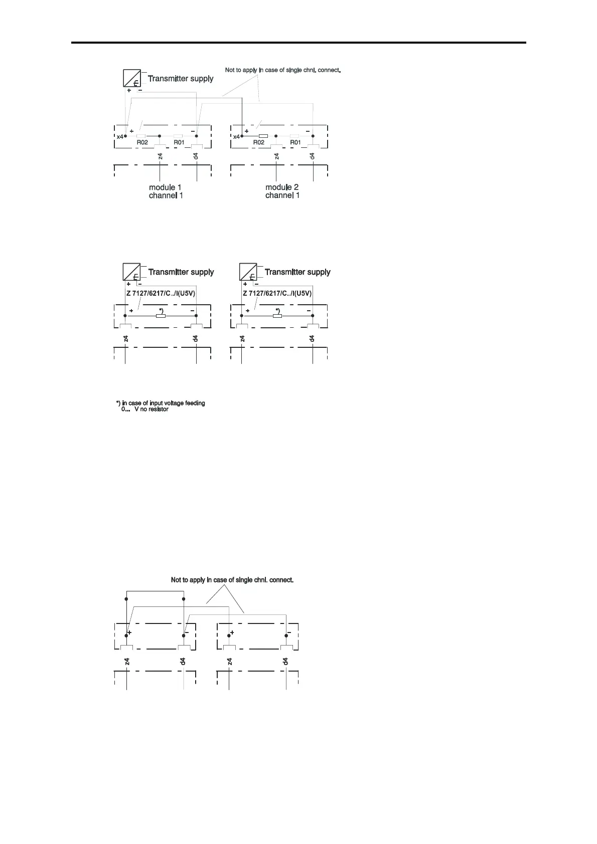
Figure 5: Redundant connection via voltage divider
Figure 6: Current or voltage connection of redundant transmitters (evaluation in the user
program)
Occupation of not used inputs
Not used voltage inputs 0 ... 5 V have to be terminated with jumpers. Not used current inputs
are terminated with the shunt, not used voltage inputs 0...10 V with the voltage divider in the
cable connector.
Not used inputs, redundant connection
Example is for channel 1.
Installation of jumpers outside of the cable connectors on the terminals:
Figure 7: Voltage input 0...5 V
Note: Regard to the internal resistance
of the transmitter voltage supply
F 6217 F 6217
Z 7127/6217/
C../U10V/R2
Z 7127/6217/
C2/U10/R1
R01, R02 = 1.96 kOhm
HIMA
art no.:000710192
F 6217 F 6217
module 2
channel 1 or
module 1
channel 2
module 1
channel 1
Z7127/6217/
C../U5V/R2
Z7127/6217/
C2/U5V/R1
F 6217 F 6217
module 1
channel 1
module 2
channel 1
 Loading...