F 6221 (0625)
322
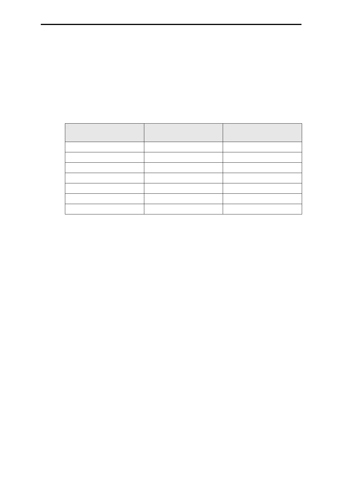
4.8 Maximum cable length and load in the transmitter circuit
The maximum additional load Rb in the transmitter circuit is calculated as follows:
Rb additional load
U
TC switch-off limit for the transmitter supply voltage monitoring
UT
min minimum supply voltage of the transmitter
I
max maximum current to be measured
The contact resistances of the clamps
must be considered. When planning the Ex circuits the
line inductance and the line capacitance for the respective line length have to be considered.
The cable to the transmitter must be shielded twisted-pair.
4.9 Start-up
Before the first system start-up, an Ex-expert has to check whether the system has been cor-
rectly installed, especially the supply voltage connections and the connections of the intrinsi-
cally safe circuits.
4.10 Maintenance
In case of a failure, the defective module must be replaced with the same type or with another
approved type. Any repair work must only be carried out by the manufacturer.
4.11 Project planning in ELOP II
• Each input channel is configured via the HF-AIX-3 software function block. The trans-
mitter supply voltage monitoring must be enabled in the software function block.
• The parameterization of the module must be performed according to the operating
system manual for the currently used version of the operating system. Especially the
chapter about the noise blanking has to be regarded.
Setting: Safety time
≥ 3 x watchdog time.
• For each input channel, the corresponding error bit must be set. The channel error bit
must be evaluated in the user programs in a way which leads to safety-related beha-
vior of the corresponding input channel.
• For resetting a channel error, the recalibration input of the HF-AIX-3 software function
block must be set to TRUE twice for at least one PLC cycle.
Spreading the measuring values (this can be configured in the HF-AIX-3 software function
block) will result in an increase of the relative error by the spreading factor.
Max. transmitter supply
voltage UT
min
Max. length of line
at 0.2 mm²
Max. length of line
at 0.5 mm²
14.5 V 135 m 312 m
14 V 271 m 625 m
13.5 V 407 m 937 m
13 V 543 m 1250 m
12.5 V 679 m 1562 m
12 V 815 m 1875 m
11.5 V 951 m 2187 m
Table 3: Max. cable length and load in the transmitter circuit
Rb
U
TC UTmin–()
I
max()
------------------------------------
()50()– Ω
16V 14V–
20mA
--------------------------50Ω–50Ω===