F 8621A (0606)
354
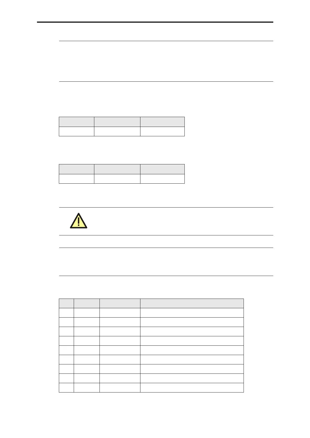
Settings S1...S4 for RS 485
Interface 1:
Interface 2:
Pin assignment of the interface RS 485
Note
If a Profibus-DP communication module F 8628 / F8628X or an Ether-
net communication module F 8627 / F 8627X is used in addition to the
coprocessor module F 8621A the software function block HK-COM-3
(from ELOP II V 3.5 BS 41q/51q V 7.08 (0214)) with proper parameter-
ization has to be set up.
S1 S2
RS 485 ON OFF
Table 1: Interface 1
S3 S4
RS 485 ON OFF
Table 2: Interface 2
Other settings as given in the table are not admissible.
Note The redundant connection to a process control system is made via two
redundant modules, each with a BV 7040.
The connection to an ELOP II bus is made via a cable BV 7046.
Pin RS 485 Signal Explanation
1 - - not used
2 - RP 5 V, decoupled by diodes
3 A/A’ RxD/TxD-A Receive/Transmit Data A
4 - CNTR-A Control signal A
5 C/C’ DGND Data Ground
6 - VP +5 V, power supply
7 - - not used
8 B/B’ RxD/TxD-B Receive/Transmit Data B
9 - CNTR-B Control signal B
Table 3: Pin assignment of the interface RS 485