H 7020 (0606)
494
Wiring on the Terminal Module
Diodes for inverse polarity protection
For wiring with input modules diodes are soldered between X17/X19, X18/X20.
Diode 1N5624 3A / 200 VDC
HIMA Part-No. 26 8200 015
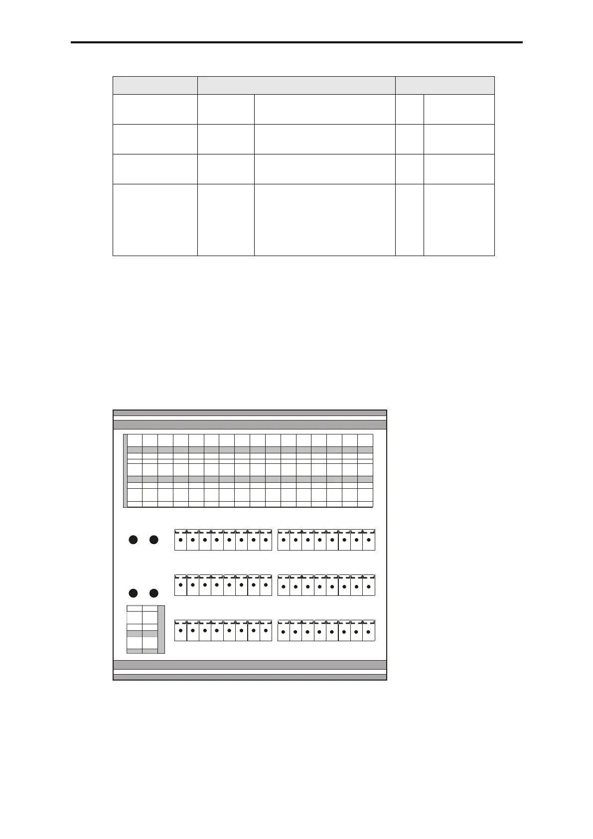
Mechanical Design
The designators (L+,L-) on the labels D and F are project dependent.
Figure 2: Mechanical Design H 7020
Designator Type Contact
F X1 - X16 double-level terminal
spring-cage connection
16x 1-pin
E X17 - X20 soldering points (for soldering
of jumpers or diodes)
4x
D X21 - X22 terminal
spring-cage connection
2x 1-pin
A, B, C X23 - X28 Phoenix Headers
Accessories:
Phoenix Combicon Connector
FK-MCP 1,5/8-ST-3,81
HIMA Part-No. 52 0000 002
6x 8-pin
Table 1: Wiring on the Terminal Module
X1 X2 X3 X4 X5 X6 X7 X8 X9 X10 X11X12X13X14X15 X16
F
E
D
CBA
X23
X25
X27
X24
X26
X28
X17
X18
X22X21
X19
X20
FRONT
RE RA