H 7505 (0630)
504
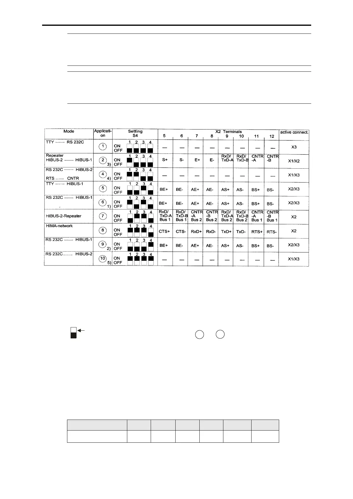
Table of the operating modes
Transmission rates
20 mA ≤ 19,200 bps
V.24
≤ 57,600 bps
RS 485 and RS 422
≤ 600,000 bps
Cable cross sections for power supply
Note
Choice of power supply connection on X2 or X4, depending on the
mounting position.
Operating data 24 VDC / 120 mA
Note With exceeding the ambient temperature of 50 °C the transparent
cover will be deformed.
This will not influence the function of the module.
max. cable length 250 m 400 m 530 m 800 m 1300 m 2500 m
Cross section (mm
2
)
0.5 0.75 1.0 1.5 2.5 4.0
1) constant status signal (= H7503 A)
2) active status signal (= H 7503)
3) only at the end of the HIBUS-1
4) since 1992 (ref. to planning list), PLESY-P V ≥ 1.5
The DTR signal controls the direction of the H 7505,
basic direction RS 485 --> RS 232C
5) till 1992 (ref. to planning list), PLESY-P V ≤ 1.4
The CNTR signals of the RS 485 interface control the direc-
tion of the H 7505, basic direction RS 232C --> RS 485
Application 4 and 10 : Setting in ELOP II, Wizcon
(connection via Modem, fiber optic cable)
V.24 = RS 232 C (H50, PC, PLS)
20 mA = TTY (H30)
HIBUS-2 = PROFIBUS (Hardware compa-
tible)
= RS 485 (H51)
HIBUS-1 = RS 422 (H7503)
white switch
Legend:
 Loading...