B 4236-1/-2 / H41q-H/HR (0605)
72
• H41q-H / B 4236-1: max. 13 IO modules (slots 1 - 13)
• H41q-HR / B 4236-2:
7 IO modules (slots 1- 7) related to central module 1,
6 IO modules (slots 8 - 13) related to central module 2
2 Modules
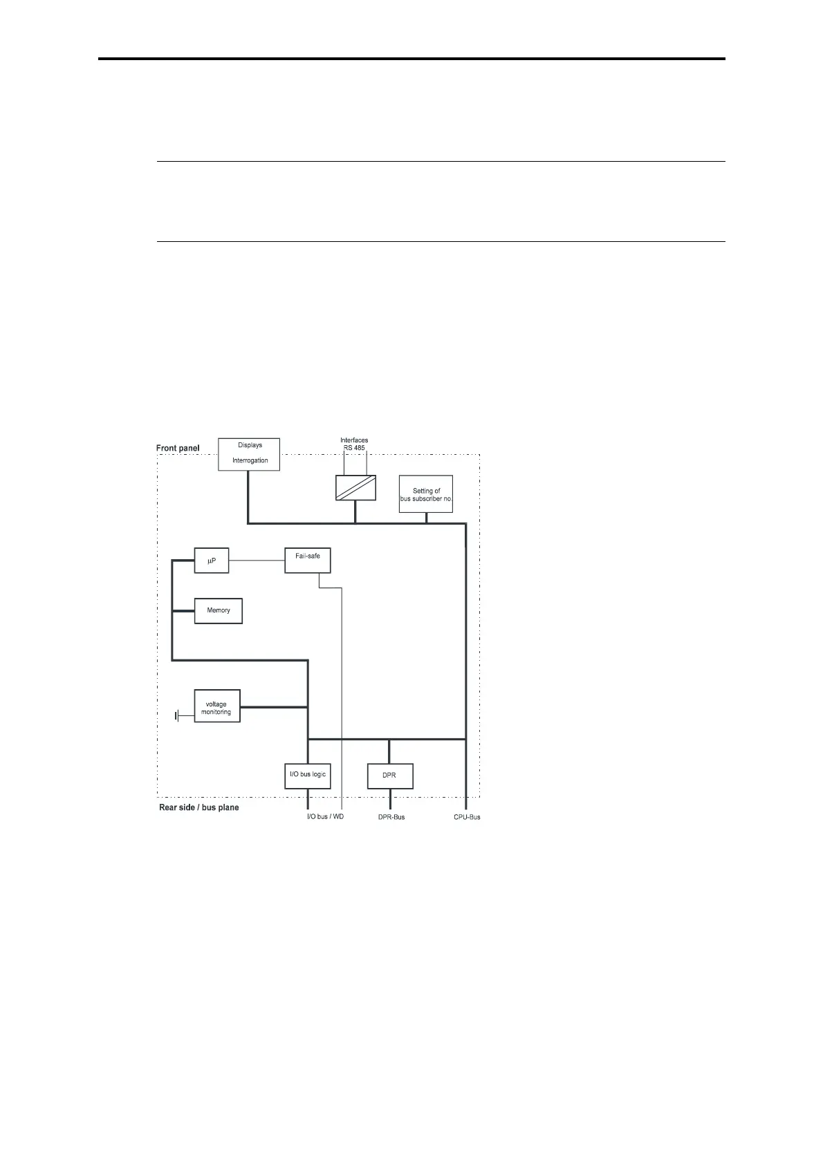
2.1 Central module F 8653X
The central module for the PES H41q-H/HR contains the essential functions demonstrated in
the block diagram of the central module:
Figure 2: Block diagram of the central module F 8653X
– Microprocessor
– Flash-EPROMs of the program memory for the operating system and the user program
usable for min. 100,000 writing cycles
– Data memory in sRAM
– 2 interfaces RS 485 with galvanic isolation. Transmission rate: max. 57600 bps
– 4digit diagnostic display and 2 LEDs for information out of the system, I/O level and user
program
– Power supply monitoring
– I/O bus logic for the connection to the input/output modules
– Hardware clock, battery buffered
– Watchdog
– Battery backup of the sRAMs via battery with monitoring
Note Operating system/resource type in ELOP II
The assembly kit is usable since operating system BS41q/51q V7.0-8.
Resource type in ELOP II: H41qce-H/H41qce-HR.
Watchdog