B 5230 / H51q-M (0605)
91
The 5 VDC output voltage of the power supply module (for the CPU, I/O and the interfaces)
are monitored by the power supply monitoring module F 7131 checking undervoltage, over-
voltage or failure.
In case of a faulty power supply module the operating system of the CPU informs the user pro-
gram via a system variable.
In case of a 5 VDC system power failure a lithium battery on the central module buffers the
hardware clock and sRAM on the central module.
The sRAM memory of the coprocessor module is buffered via two lithium batteries on the pow-
er supply monitoring module F 7131.
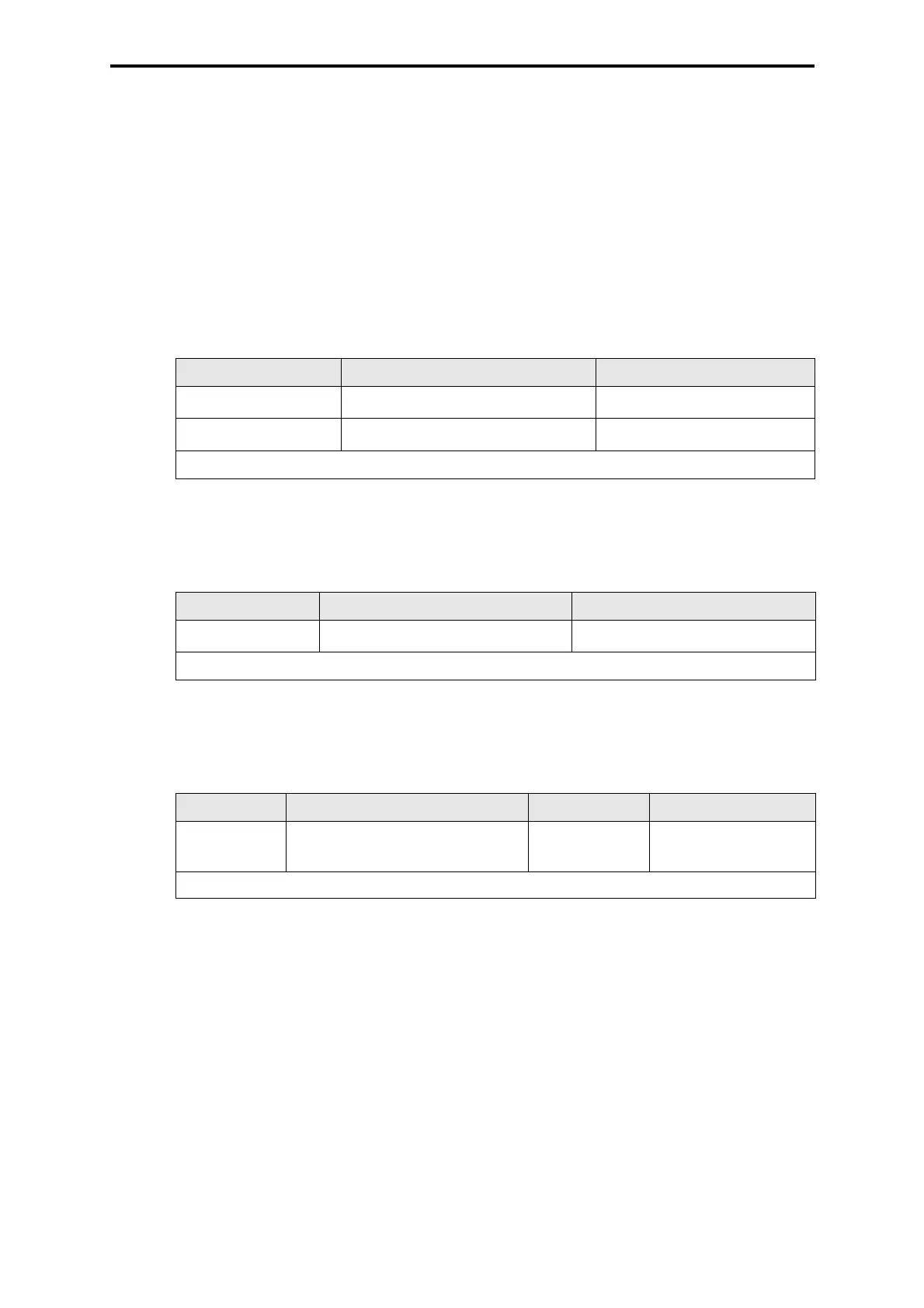
4.1.5 Output 5 VDC
4.2 Output WD
4.3 Connection of the monitoring loop (for fuses and fans)
Connection Wire and connection Use
XG.2: +5 V
YE 2 x 2.5 mm
2
, Faston 6.3 x 0.8
Supply I/O subrack (B 9302)
XG.3: GND
GN 2 x 2.5 mm
2
, Faston 6.3 x 0.8
Supply I/O subrack (B 9302)
GN = Color code green YE = Color code yellow
Table 3: Output 5 VDC
Connection Wire and connection Use
XG.1:2 (4)
GY 0.5 mm
2
, wire end ferrule
WD to I/O subrack
GY = Color code gray
Table 4: Output WD
Connection Wire and connection Fusing Use
XG.26:4/5/6
GY 0.5 mm
2
, Faston 2.8 x 0.8
max. 4 A slow
blow
Floating NO/NC con-
tact for signaling
GY = Color code gray
Table 5: Connection of the monitoring loop
 Loading...