to determine the factory congured operating mode. The operating
mode can be recongured easily using a computer attached to the
Engineering Port. Contact Honeywell Analytics or your local agent for
more information.
Note: With software versions prior to 1V6, the analogue output signal
may not properly reect the sensor signal when the sensor signal
is outside the normal measuring range.
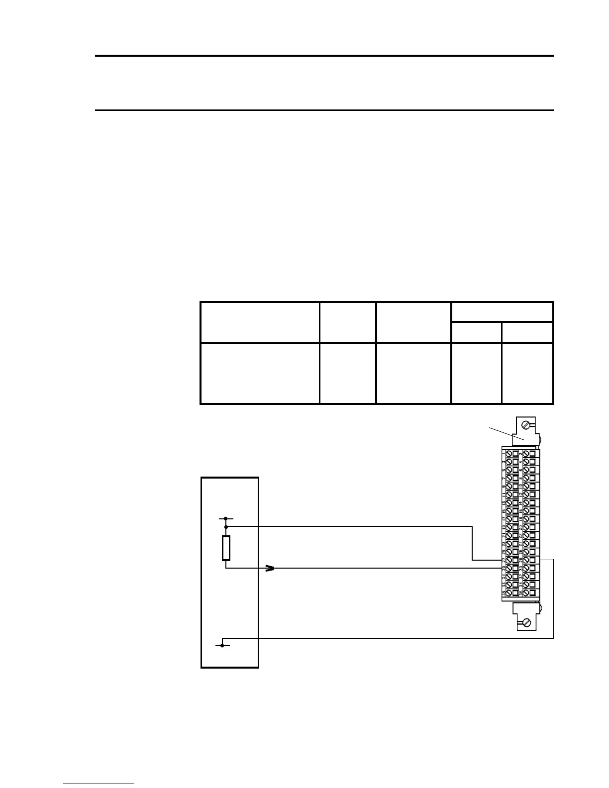
The analogue outputs can be connected to voltage input device (eg.
chart recorders) by including an external sense resistor in series with
each loop and connecting the device input in parallel with the resistor.
ie. Use a 100 ohm resistor and select an input range of 2V on the chart
recorder.
The recommended connections are:
Channel Analogue Power Supply
Output 0V 24V
Quad Relay 1 29 28 27
Interface Connections 2 30 28 27
3 31 28 27
4 32 28 27
Isolated Analogue Output Connection with Power Sourced from
Programmable Logic Controller Using Sink Module
Analogue Channel 1
Analogue OV
0V
+24V
(18V to 40V)
Quad Relay Interface Card 05704-A-0121
Four Channel Control Card Fitted with:
Analogue Output Module (Sink) 04200-A-0145
Programmable
Logic
Controller
29
28
27
Analogue 24V

 Loading...


