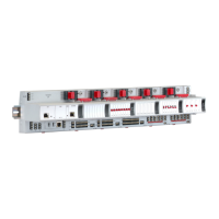
12.3 4 - 20mA Loop Powered Sensor Connections
Loop powered sensors require a two wire connection and the sensor
documentation will indicate the positive and negative loop connections,
usually brown and blue respectively.
AttheSystem57endoftheeldcablethetwosensorwiresshould
be connected to the S (positive) and 01 (negative) terminals of the
appropriate channel on the Quad Relay Interface Card that is attached
to the required Four Channel Control Card.
The sensor cable screen or steel wire armour (or braid), as appropriate,
should be connected to the system (protective) earth. This can be
achieved where the cable enters the cabinet by using a metal cable
gland, or by other suitable means, and avoiding any screen 'tails' within
the cabinet.
Where the cable consists of a separate screen sheath and wire armour
(or braid), the armour should be connected, at the cabinet entry, to the
protective earth and the screen sheath should be connected to the
GROUND terminal of the Quad Relay Interface Card or to a suitable
instrument earth point.

 Loading...


