The following sections outline how to calculate the maximum line
resistance for catalytic sensors, loop powered sensors and transmitters
powered from the System 57. See Section 11.3 for a guide on cable
selection.
11.3 Cable Resistance Guide
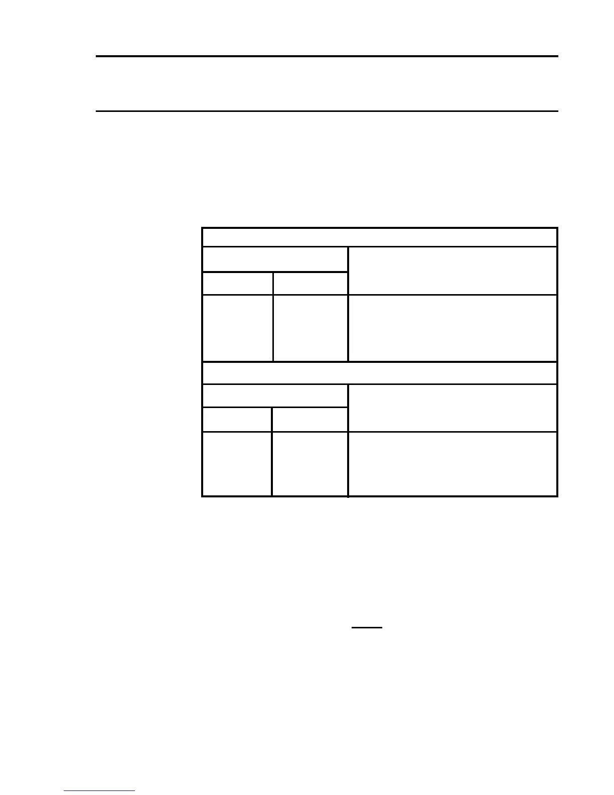
Aguidetotheresistanceofvariouscoppercablesizesisgivenbelow:
Solid Copper Conductor
Cross Sectional Area Maximum resistance at 20°C
(mm˝) AWG (ohm/km)
0.50 21 36.8
0.75 19 24.5
1.00 18 18.4
1.50 16 12.3
2.50 14 7.4
Stranded Copper Conductor
Cross Sectional Area Maximum resistance at 20°C
(mm˝) AWG (ohm/km)
0.50 21 36.8
0.75 19 24.5
1.00 18 17.6
1.50 16 11.7
2.50 14 7.4
11.4 Catalytic Sensors
The maximum line resistance of cabling for a catalytic sensor varies with
the current and voltage requirements of the type of sensor installed. It is
alsosubjecttoamaximumof10VpermittedacrossterminalsSandNS
at the Quad Relay Interface Card.
Maximum line loop resistance is calculated as follows:
10 - V
s
R
L
=
I
s
Where: R
L
= Total Line Resistance (ohms). Including sensor.
V
s
= Sensor Voltage (V)
I
s
= Sensor Current (A)

 Loading...


