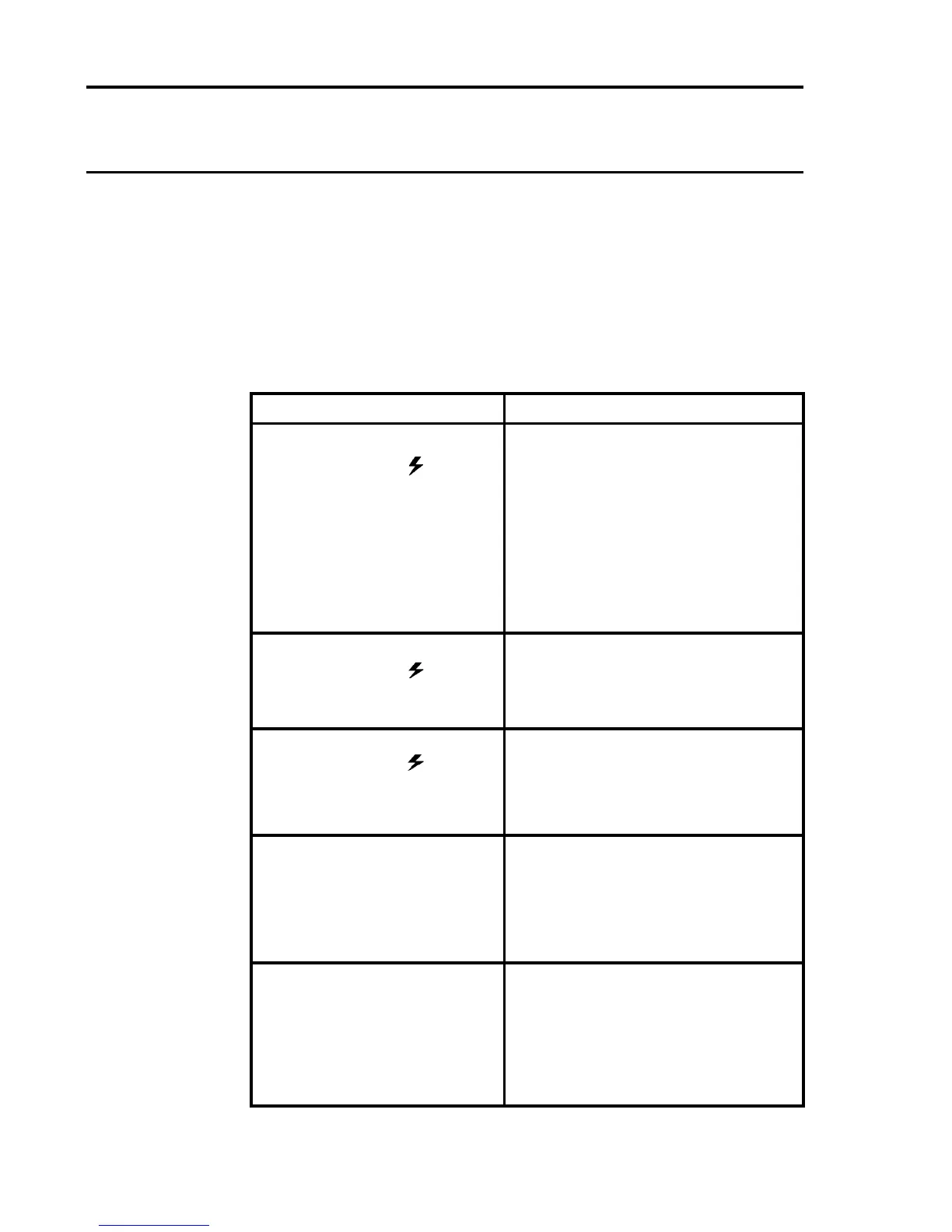
Action
Disconnect TB1 and measure the
voltage between the +24V dc and
0V terminals.
If the voltage is correct, remove the
DC Input Card and check the fuse
FS1.
If the voltage is not correct, check
the system power supply unit.
The dc input voltage is too low.
Check dc voltage at the DC Input
Card terminals.
There is a hardware fault.
Switch power of and then on again.
If problem persists, check the
diagnostic printout for error codes
Check that the ac mains voltage is
between 85V and 264V at the power
supply ac connection wires.
If yes, replace the 50W Power
Supply Module.
Check that power is being applied to
the control card from the backplane
or Quad Interface Card as applicable
and the display still does not read,
replace the control card.
6. FAULT FINDING
The following table provides a guide to diagnosing various conditions
within the operation of System 57.
Note: In addition to some of the following fault codes that may be
displayed, the control card ATTN LED will ash one second on/one
second off should a hardware or software fault be detected on the
control card.
Fault
The Engineering Card front
panel power on (
) green
LED extinguished.
The Engineering Card front
panel power on ( ) green
LEDashesatapproximately
two second intervals.
The Engineering Card front
panel power on ( ) green
LEDashesatapproximately
0.5 second intervals.
No dc voltage output from
Power Supply Unit.
No readings on a control card
display.

 Loading...


