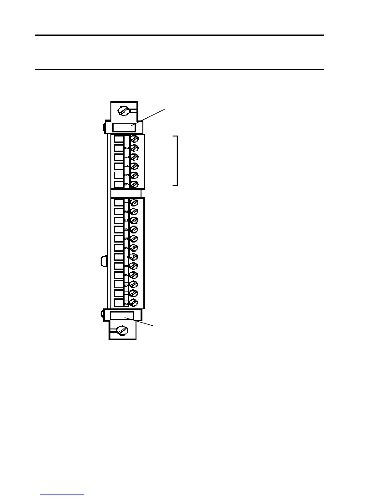
7.3 DC Input Card Front Access Connections
TB2
1
2
3
4
5
6
TB1
1 Ground
2 Ground
3 0V Out (Fused)
4 +24V Out (Fused)
5 0V In (AUX 2) or 0V Out (AUX 1)
6 +24V In (AUX 2*) or +24V Out (AUX 1)
7 0V In (AUX 1)
8 +24V In (AUX 1)
9 0V In (PSU 2) or 0V Out (PSU 1)
10 +24V In (PSU 2*) or +24V Out (PSU 1)
11 0V In (PSU 1)
12 +24V In (PSU 1)
For Engineering Card Modules
(Functions will vary)
Note: For 5704 systems with more than eight catalytic control cards, it
is recommended that the dc power is connected direct to each
channels' Quad Relay Card.
* PSU 1 and PSU 2 (and AUX 1 and AUX 2) must be
compatible with parallel connection.
Slot Location Label
Label for
User Terminal
Reference

 Loading...


