15.2 Individually Powered Control Cards
Notes: 1. In individually powered control systems a DC connection is
still required to the DC Input Card in order to provide power
to the Engineering Card.
2. The supply to each control card must be externally fuse rated
at 2A maximum.
Individually powered control cards may be required for two reasons:
a. Where the local or other regulations dictate individual connections
in order to achieve the highest integrity for power distribution.
b. In densely populated racks to reduce the current load on the
backplane.
The System 57 DC Input Card supply is fused at 10A and to ensure
reliableoperationofthesystem,themaximumcontinuouscurrentow
in the rack backplane should be less than 8A. In 16 channel racks,
substantially populated with four channel catalytic control cards, this
backplane current can be exceeded, especially where long sensor
cable runs are present. Therefore, as a general rule, where more than
eight catalytic control cards are used in a single rack, these should be
powered using the individually powered scheme.
Individual powering of a four channel control card is easily achieved
as follows:
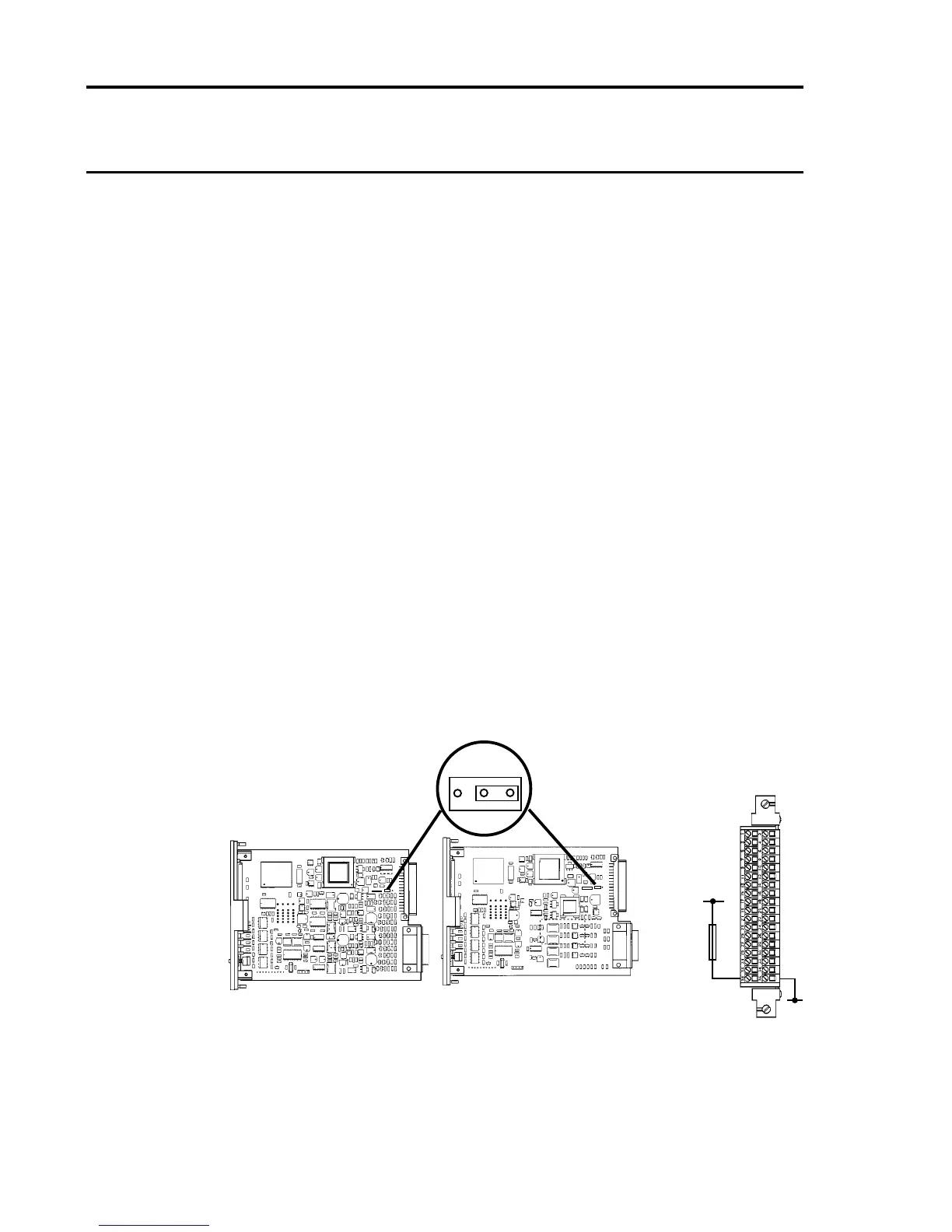
(1) On the Four Channel Control Card, remove the link LK1 from
position1-2andretinposition2-3asshownbelow:
(2) Wire the +24V DC power supply to the respective Quad Relay
Interface Card terminals 35 (+24V) and 36 (0V) as shown above:
Four Channel Control
Card Catalytic Input
Four Channel Control
Card 4 - 20mA Input
LK1
35
36
+24V
(18V to 32V)
0V
1 2 3
External
Fuse 2A
Maximum

 Loading...


