13. OUTPUT CONNECTIONS
13.1 Relay Outputs
Note: The FAULT relay is permanently configured for normally
energised operation in the non-fault condition.
CAUTION
When mains ac is connected to the relay contacts:
a. The ac supply should be fused at 5A maximum.
b. A safety earth connection should be made to the ground
terminal of the relay card.
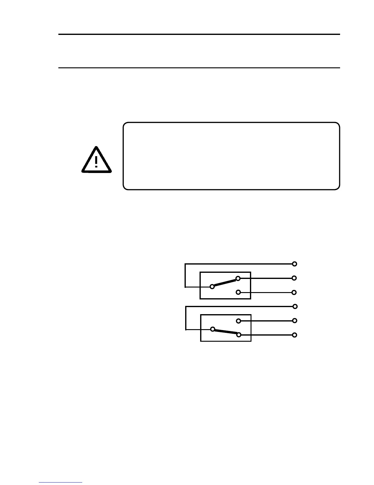
There are two relay card types providing different levels of alarm relay
capability (See Chapter 2 Section 5).
The cabling to the relays should where possible be kept away from the
sensor cabling, especially those cables carrying mains supplies. The
followinggureshowstherelaycontactconnectionsasshownonthe
terminal block.
Com
NO
NC
Energised
Contact
Position
Com
NO
NC
De-energised
Contact
Position
De-energised and Energised Relays Showing Contact Positions
Thealarmrelaysmaybeconguredforeithernormallyde-energisedor
normallyenergisedoperation.Checkthecongurationsheetsupplied
with the system to determine the operating mode of the relays on each
channel.Theenergisationmodeoftherelayscanbereconguredeasily
using a computer attached to the Engineering Port. Contact Honeywell
Analytics or your local agent for more information.

 Loading...


