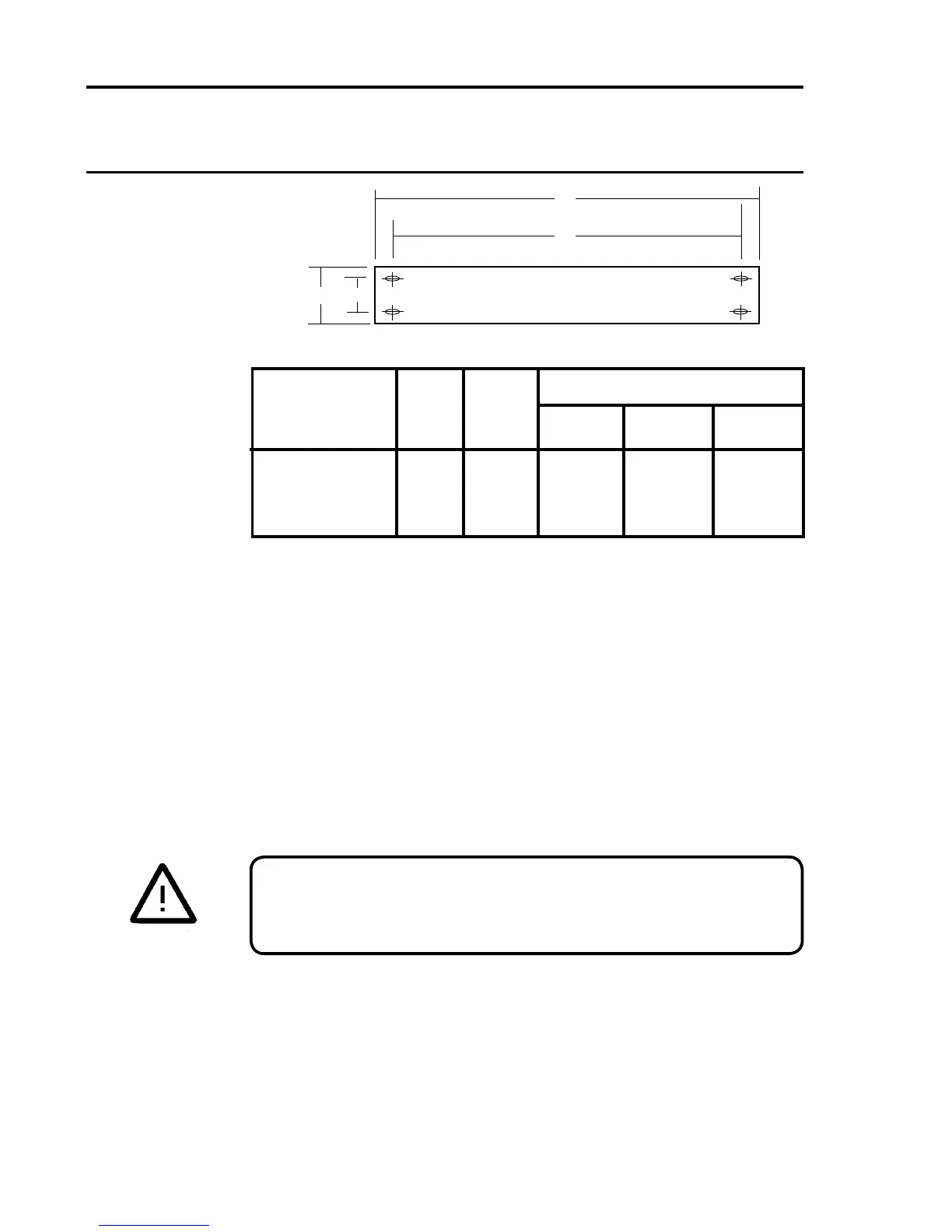
AC to DC PSU Table of Sizes (mm)
PSU Assembly A B Clearance
Width Height Depth
8 Way 279.4 261.9 222 41 190
16 Way 482.6 465.1 443 41 190
(2) Insert the rack into the aperture and secure using M6, or similar
bolts,throughthefourmountingholeslocateduponthefrontange
plates.
(3) Ensure adequate support at the rear of rear access racks.
(4) Prepare and connect the cable ends to Quad Relay Interface and
ExpansionRelay Cardsterminals. Forterminalidentication see
Chapter 2. Where possible keep sensor cables separate from the
other wiring.
(5) Ensure that the rack is properly earthed by connecting a suitable
earth cable to the earth stud located at the rear of the rack.
CAUTION
Do not apply power to the System 57 until the commissioning
procedure has been read and understood. See Chapter 5.
10. RACK INSTALLATION
The 16-way 3U high rear access and 6U high front access racks are
suitable for mounting in standard 19" (483mm) wide Mounting Frames.
Thesearettedasfollows:
A
31.8
5.9
43.6
8.4
B

 Loading...


