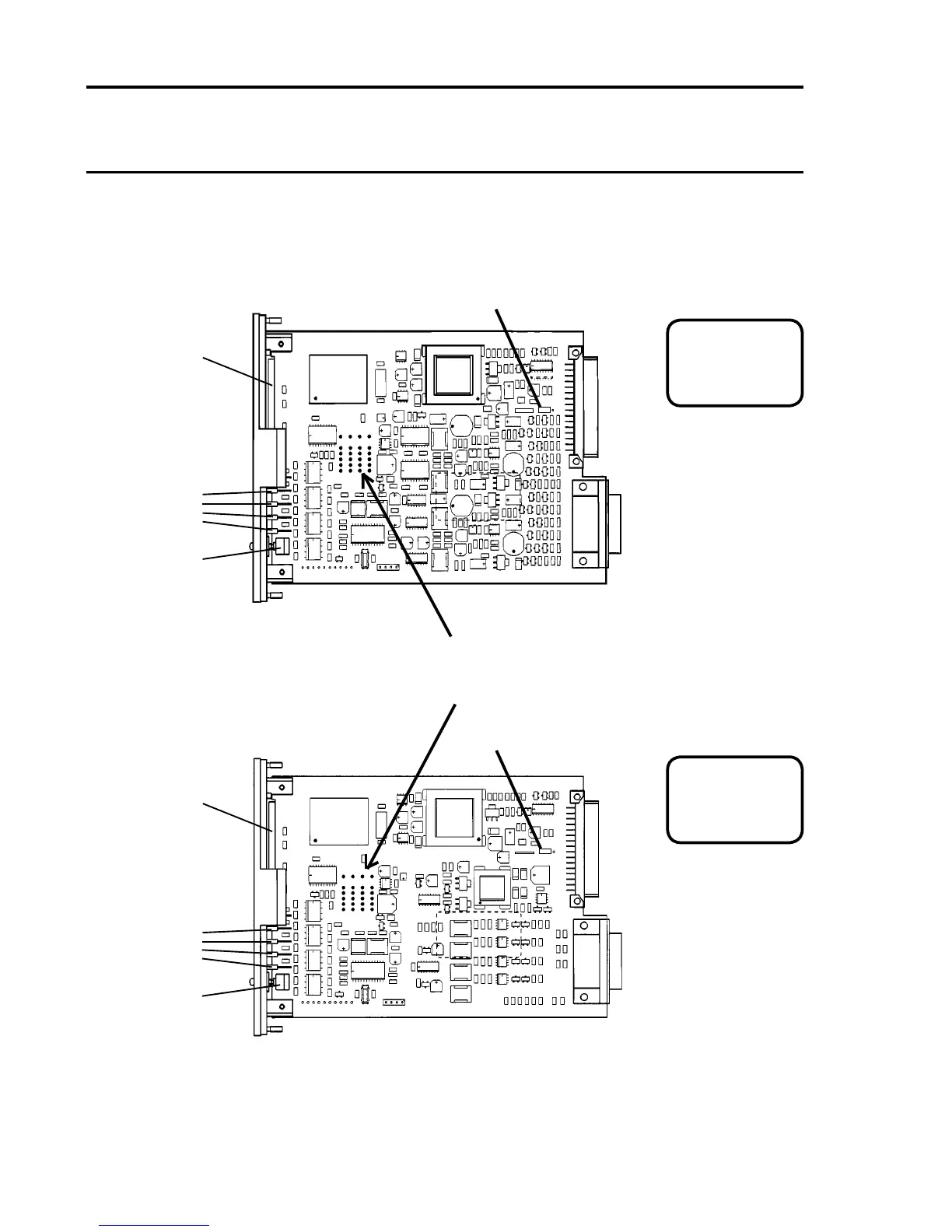
4.4 Physical Layout
The physical layout of the Four Channel Control Card is shown below.
AnalogueOutputModules,whentted,plugintochannelsocketsas
shown:
Plug-in Sockets for Analogue Output Modules
(From left to right - Channel 1 2 3 4)
Liquid Crystal
Display
LEDs
Reset/Select
Push Button
Switch
32-Way Connector (SK2)
To Backplane
26-Way D Type Connector (SK1)
To Quad Relay Interface Cards
Liquid Crystal
Display
LEDs
Reset/Select
Push Button
Switch
32-Way Connector (SK2)
To Backplane
26-Way D Type Connector (SK1)
To Quad Relay Interface Cards
4 CHANNEL
CONTROL CARD
05704-A-0144 Iss.
CATALYTIC INPUT
Ser/Batch No.
4 CHANNEL
CONTROL CARD
05704-A-0145 Iss.
4 - 20mA LOOP INPUT
Ser/Batch No.
LK1 tted to pins 1 - 2
LK1 tted to pins 1 - 2 Identication Label
Identication Label

 Loading...


