a. Routeing of the 24V dc input from the DC Input
Card to the backplane of the rack.
b. A backplane serial communications controller and
monitor.
c. A time and date reference.
d. An RS232 external engineering interface.
e. Depending upon the security level, the operation
of the following rack facilities:
Catalytic sensor head current monitoring and
adjustment.
Alarm set point checking, adjustment and
testing.
Sensorsignalzeroadjustment.
Sensorsignalspanadjustmentandsettingof
sensor life monitoring values.
Sensor line monitoring.
Enabling of control card alarm inhibit.
Checking and adjustment of the system
clock.
f. Self validation of the operation of its circuit
components, software operation and the
backplane communications.
g. A socket for the addition of special modules that
expand the System 57 capabilities.
6.
ENGINEERING CARD PART NUMBER (05701-A-0361)
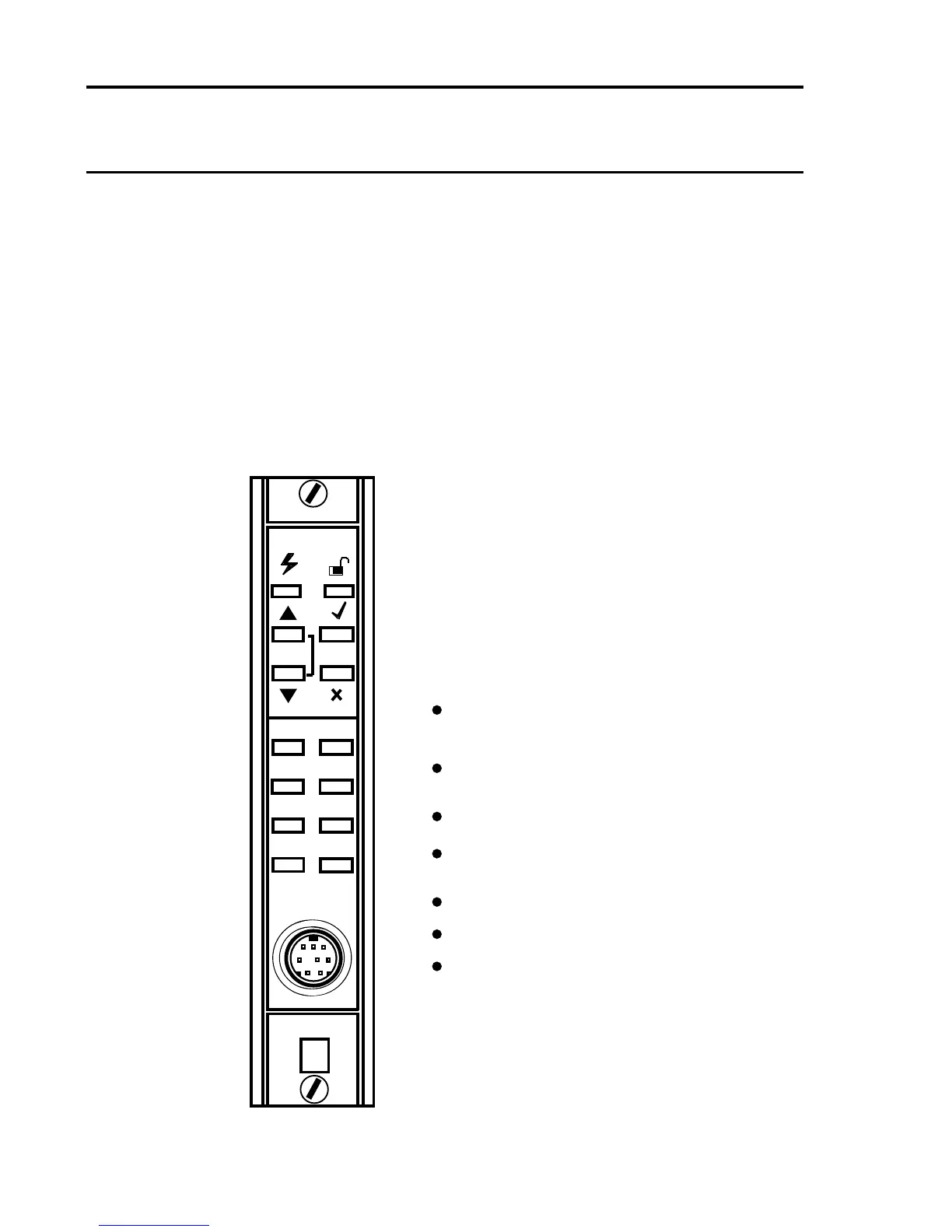
The Engineering Card is used on a System 57 rack to provide a common
interface that enables the user to perform all the required functions to
commissionandoperateeachttedcontrolcard.
The front panel is tted with a series of tactile push-buttons for the
operation of various functions, LEDs to provide rack power and
communications status and a mini DIN socket for the connection of a
serial printer, computer or an engineering key. The Engineering Key
is used to unlock functions that can alter the operation of a control
card.
The Engineering Cardis always ttedinto the right-handslot of the
rack and provides:
CLOCK
INHIBIT
1
ST
SPAN
SPAN
SIGNAL
ZERO
ALARMS
BEAD mA
PRINT

 Loading...


