4. FOUR CHANNEL CONTROL CARDS
4.1 General
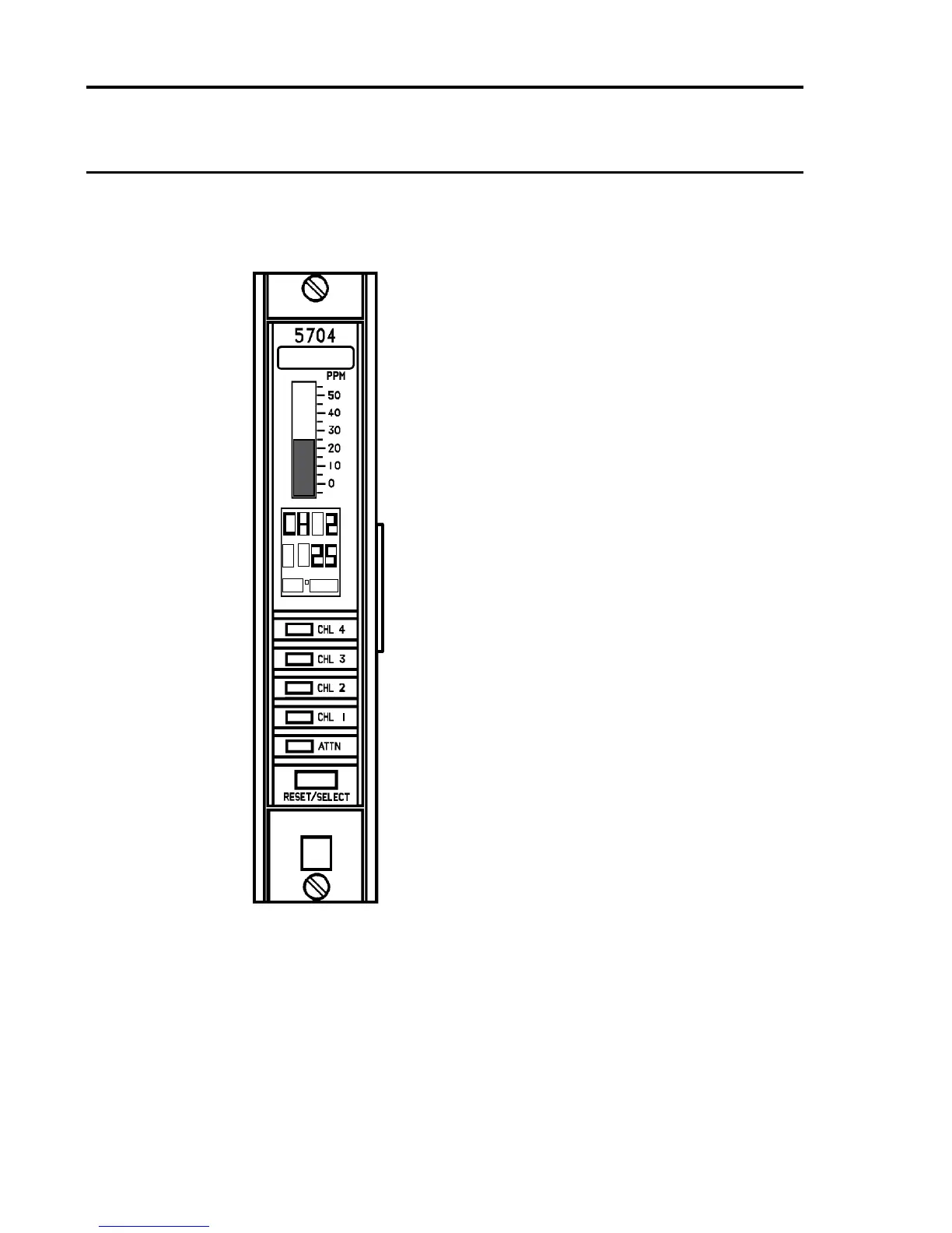
The 5704 Four Channel Control Card provides
control, display and alarm facilities for up to four
connected gas detectors. The front panel backlit
display indicates the gas reading, channel status
and channel number while LEDs are used for
alarms. A push-button is provided for resetting
the alarms and selecting the card for use with
the Engineering Card.
The operation of the control card is microprocessor
controlledandisfullydenableforawiderange
of connected gas detectors and application
requirements.Thesoftwarecongurationsetup
is stored in an EEPROM.
There are two types of control card depending
onthe typeof gas detectorbeing tted tothe
system:
a. Four Channel Control Card Catalytic Input
Part Number 05704-A-0144.
b. Four Channel Control Card 4 - 20mA Input
Part Number 05704-A-0145.
Optional Analogue Output Modules which provide
a remote output of the channel card readings can
be plugged into the Four Channel Control Card.
One module is required per channel and different
module types are available to permit either
current source or current sink as required.

 Loading...


