If the measuring resistance is in the negative supply line, a double
safety barrier must be used.
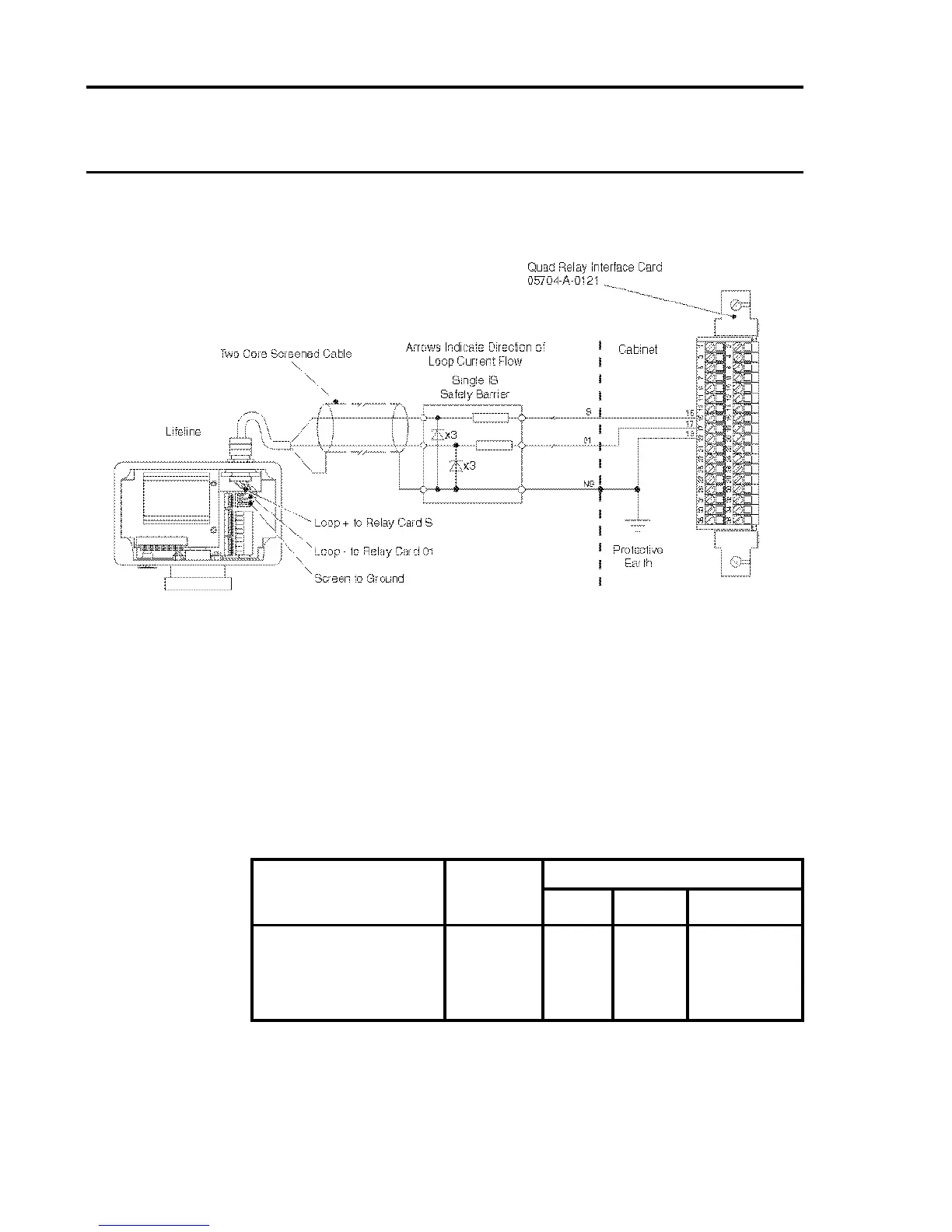
Note 1: *To ensure that the input circuit is properly referred to the safety
barrier it is necessary to connect the isolated 0V to the barrier
ground.
2: The above diagram shows the sensor connections for Channel
1. The connections for Channels 2, 3 and 4 are similar and
their pin connection numbers are shown below:
Channel Sensor Connection
S 01 0V
Quad Relay 1 15 17 19
Interface Connections 2 16 18 20
3 21 23 25
4 22 24 26
IS Lifeline Sensor With Double Safety Barrier

 Loading...


