1
2
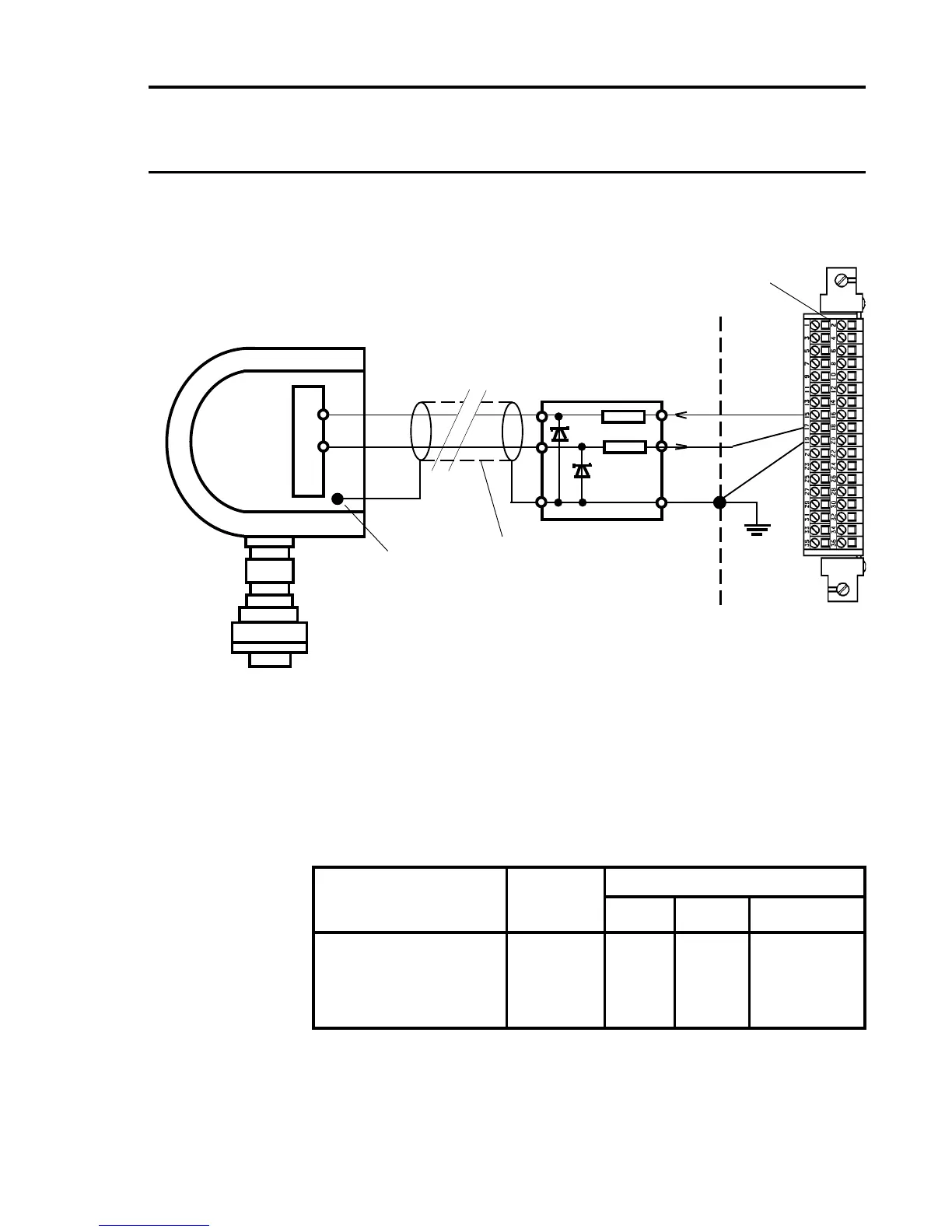
Quad Relay Interface
Card
05704-A-0121
Double IS
Safety Barrier
x 3
S
01
Arrows Indicate
Direction of Loop
Current Flow
Two Core Screened Cable
GND
IS Series 2000
Toxic Sensor
Terminal Block
Earth Stud
15
17
19
12.5 IS Transmitter Connections
If the measuring resistance is in the negative supply line, a double
safety barrier must be used.
Note: The above diagram shows the sensor connections for Channel 1.
The connections for Channels 2, 3 and 4 are similar and their pin
connection numbers are shown below:
Channel Sensor Connection
S 01 0V
Quad Relay 1 15 17 19
Interface Connections 2 16 18 20
3 21 23 25
4 22 24 26
IS Series 2000 Toxic Sensor With Double Safety Barrier
Cabinet
Protective
Earth
x 3
NS

 Loading...


