4 - 20mA (-)
0V
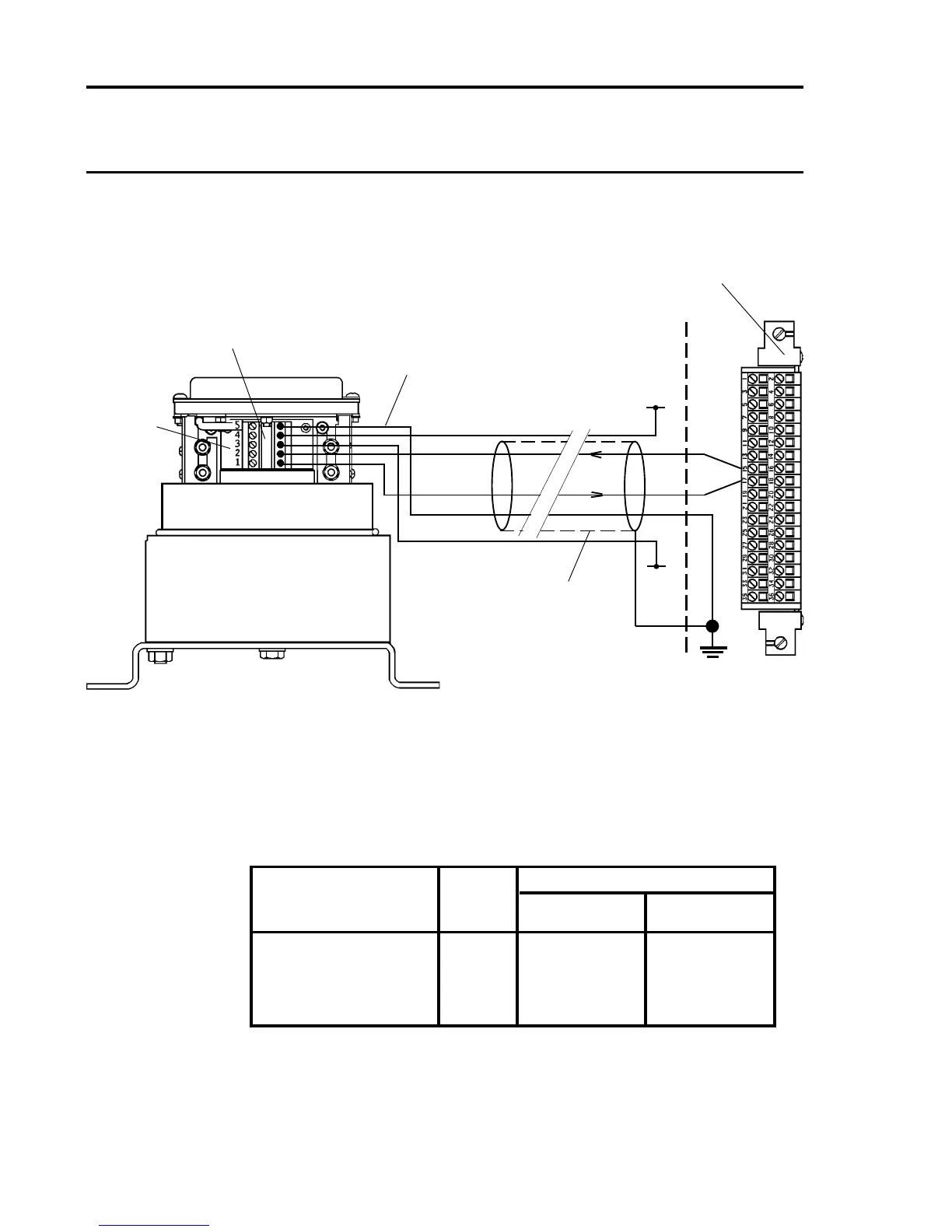
Note: The above diagram shows the sensor connections for Channel
1. Channels 2, 3 and 4 connections are similar and their pin
connection numbers are shown below:
Channel Sensor Connection
S 01
Quad Relay 1 15 17
Interface Connections 2 16 18
3 21 23
4 22 24
Four Wire Floating Signal Input, Transmitter Current Sink
Connection
Series 2000 UL
Sensor
Terminal Block
S
01
Screened
Cable
Quad Relay Interface Card
05704-A-0121
15
17
Cabinet
Protective
Earth
+24V
0V
Arrows Indicate
Direction of Loop
Current Flow
No
Links
+24V
4 - 20mA (+)
Barrier Safety Ground

 Loading...


