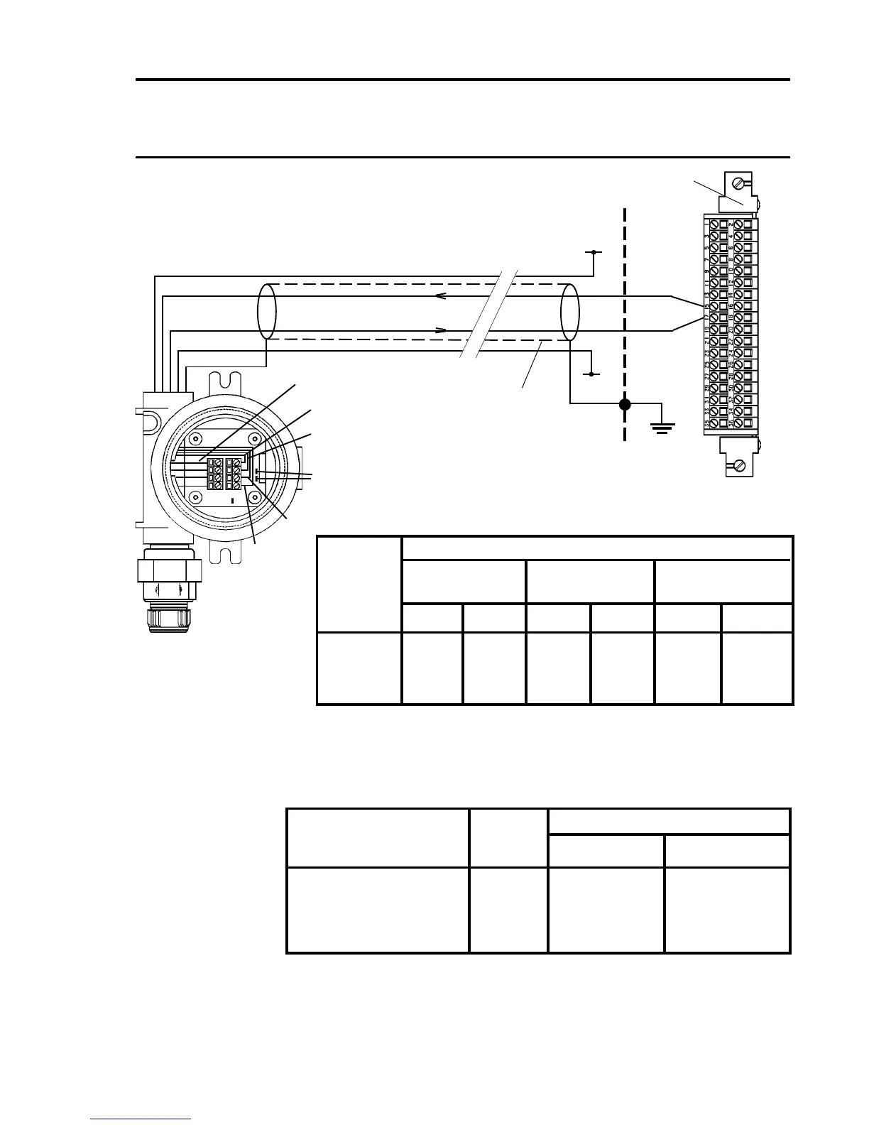
Note: The above diagram shows the sensor connections for Channel
1. Channels 2, 3 and 4 connections are similar and their pin
connection numbers are shown below:
Channel Transmitter Connection
S 01
Quad Relay 1 15 17
Interface Connections 2 16 18
3 21 23
4 22 24
Four Wire Isolated Signal Input, Transmitter Current Sink
Connection for Digi Series
Block Sensor Connections
Wiring Digi-Cat Digi-Chem Digi-Ana
Catalytic ECC Analogue
Terminal
Signal Colour Signal Colour Signal Colour
1 GND - GND - S -
2 NS Blue C Brown 01 Brown*
3 C/T White R White 0V Blue*
4 S Brown W Blue +24V
* Valid for 811 and 911. For other sensors, see sensor documentation.
1
2
3
4
S
01
Screened Cable
Arrows Indicate
Direction of Loop
Current Flow
+24V
4 - 20mA(-)
4 - 20mA(+)
0V
GND
Quad Relay Interface Card
05704-A-0121
15
17
0V
+24
4-20mA(-)
4-20mA(+)
Do not t LK2 or LK3
Sensors: 704 705
783 811
910 911
See Table for Sensor Wiring
Cabinet
Protective
Earth
+24V*
0V*
Digi Series
* 24V supply may be obtained
from either the cabinet or a
separate eld supply

 Loading...


