Channel Transmitter Connection
01 NS
Quad Relay 1 17 19
Interface Connections 2 18 20
3 23 25
4 24 26
Three Wire Control Card Current Sink, Transmitter Current
Source Connection for Digi Series (Signal Returned to 0V
Supply)
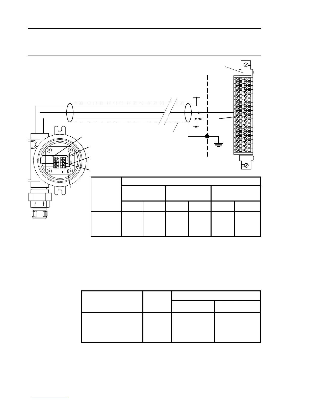
Notes: 1. Where a sensor is earthed locally, either to the Earth Stud or through the sensor
casing or mounting, to avoid earth loops the screen sheath of the cable should only
be connected at one end.
2. The above diagram shows the sensor connections for Channel 1. Channels 2, 3 and
4 connections are similar and their pin connection numbers are shown below:
+24
1
2
3
4
Block Sensor Connections
Wiring Digi-Cat Digi-Chem Digi-Ana
Catalytic ECC Analogue
Terminal
Signal Colour Signal Colour Signal Colour
1 GND - GND - - -
2 NS Blue C Brown 01 Brown*
3 C/T White R White 0V/NS Blue*
4 S Brown W Blue +24V
* Valid for 811 and 911. For other sensors, see sensor documentation.
Arrows Indicate Direction of
Loop Current Flow
+24V
4 - 20mA(+)
0V
0V
4-20mA(+)
LK2 Fitted
(For Current Source)
Sensors: 704 705
783 811
910 911
Digi Series
See Table for
Sensor Wiring
Screened Cable
01
NS
Quad Relay Interface Card
05704-A-0121
17
19
Cabinet
Protective
Earth
+24V*
0V*
* 24V supply may be obtained
from either the cabinet or a
separate eld supply

 Loading...


