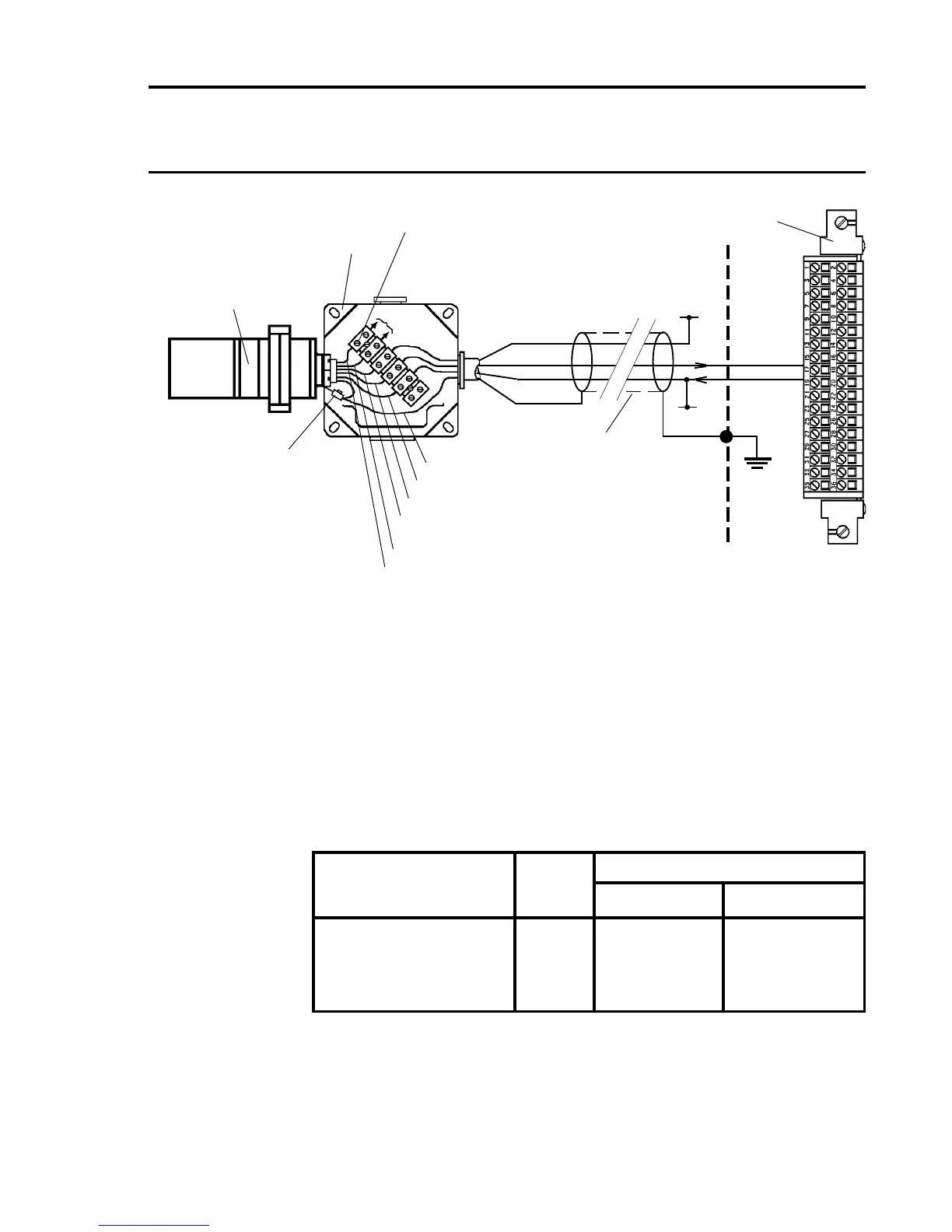
Notes: 1. Where a sensor is earthed locally, either to an Earth Stud or
through the sensor casing or mounting, to avoid earth loops
the screen sheath of the cable should only be connected at
one end.
2. The above diagram shows the sensor connections for Channel
1. Channels 2, 3 and 4 connections are similar and their pin
connection numbers are shown below:
Channel Sensor Connection
01 NS
Quad Relay 1 17 19
Interface Connections 2 18 20
3 23 25
4 24 26
Three Wire Control Card Current Sink, Transmitter Current
Source Connection for Searchpoint Optima Plus
(Signal Returned to 0V)
4 - 20mA (-)
-
Earth
Terminal
Terminal
Block
Junction
Box
Arrows Indicate
Direction of Loop
Current Flow
Green/Yellow - Ground
Black - 0V DC Supply
White - 4 - 20mA Output
Red - +24V Supply
Blue Communications
Orange Link to SHC1
SHC1
Searchpoint Optima Plus
Congured for current
source
Screened Cable
01
NS
Quad Relay Interface Card
05704-A-0121
17
19
Cabinet
Protective
Earth
+24V*
0V*
* 24V supply may be obtained
from either the cabinet or a
separate eld supply
+24V
0V
GND

 Loading...


