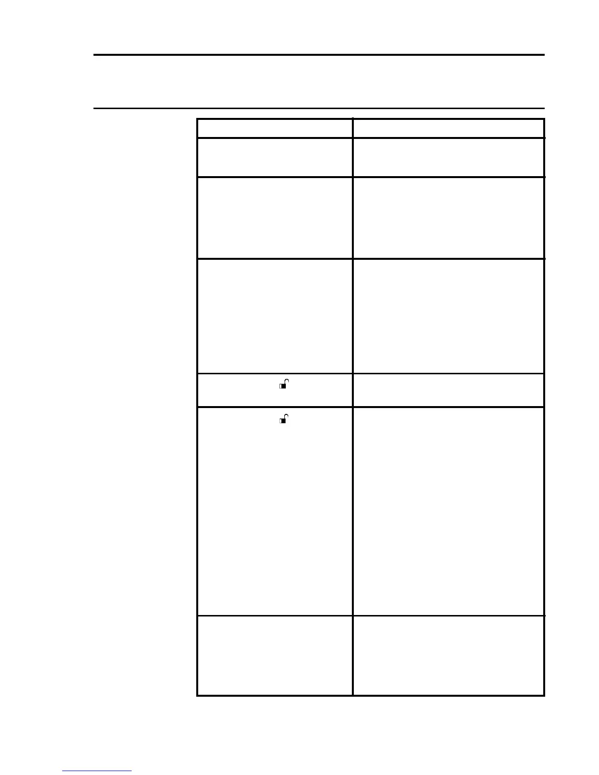
Fault
An error message is
displayed.
A CHL LED indicates a fault
conditionbyashingamber
(one second on/one second
off).
A CHL LED indicates an
inhibit condition by showing
continuous amber.
The unlocked (
) LED is
illuminated.
The unlocked ( ) LED is
ashing.
The CHL LED indicates an
alarmconditionbyashing
red but no gas reading
indicated.
Action
Check the error code tables in
Section 5 for explanation.
Check the message display for
an error code. See Section 5 for
explanation of error codes.
Check channel sensor connection
and operation.
Wait for at least 255 seconds to see
if the LED extinguishes.
Insert the Engineers Key into the
Engineering Card and then operate
the INHIBIT push-button. This
should toggle the inhibit LED on
and off, otherwise check the remote
inhibit level.
Remove the Engineering Key from
the Engineering Card.
Check that all the control cards are
ttedtotherackandareworking.
If a card has been removed
deliberately,ttheEngineeringKey
into the Engineering Card socket
and then remove the key again.
Select each control card in turn
and, using one of the Engineering
Card functions, check that
communications exist between
the selected control card and
Engineering Card.
Check that the dc power supply is
more than 16V.
Press the RESET/SELECT push-
button momentarily to remove the
latched alarm condition.

 Loading...


