5-20
MAN0448_Issue 13_ 01-2010 5704 Control System
005704-M-5001 A03249
CHAPTER 5 - COMMISSIONING AND
MAINTENANCE INSTRUCTIONS
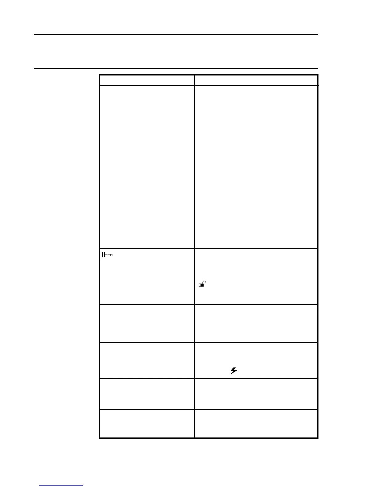
Action
Check to see if the channel is in the
inhibited condition and if necessary
remove the inhibit.
Check to see that the type of relay
interfacecardttedcansupportthe
expected alarm.
Checkthechannelcardconguration
toseethattherelayisconguredfor
the expected operation.
Swop the relay interface card with
another of the same type and test
relay action by using the Engineering
Card alarm test function.
Engineering Card has no
EngineeringKeytted.
Ifkeyisttedbuttheunlocked
(
) LED is not illuminated check
the condition of Engineering Key and
replace if necessary.
The function selected is not available
on the channel hardware present.
Select a channel card.
Check that the Engineering Card
power on ( ) LED is illuminated.
Press the RESET/SELECT push-
button momentarily to remove
latched update alarm conditions.
Check whether a channel has been
left in the alarm test mode and
remove test mode.
Fault
There is no relay operation
and a CHL LED indicates
either:
a. an alarm condition by
ashing red.
OR
b. slow redashone
second on/one second
off.
OR
c. a fault condition by
ashingamberone
second on/one second
off.
OR
d. an inhibit condition by
showing continuous
amber.
symbol showing on the
message display.
XXXX is displayed on the
message display when an
engineering function has
been selected.
The engineering push-
buttons have no effect.
TheATTNLEDashes
rapidly but no gas reading
is indicated.
The ATTN LED is
continuously on.

 Loading...


