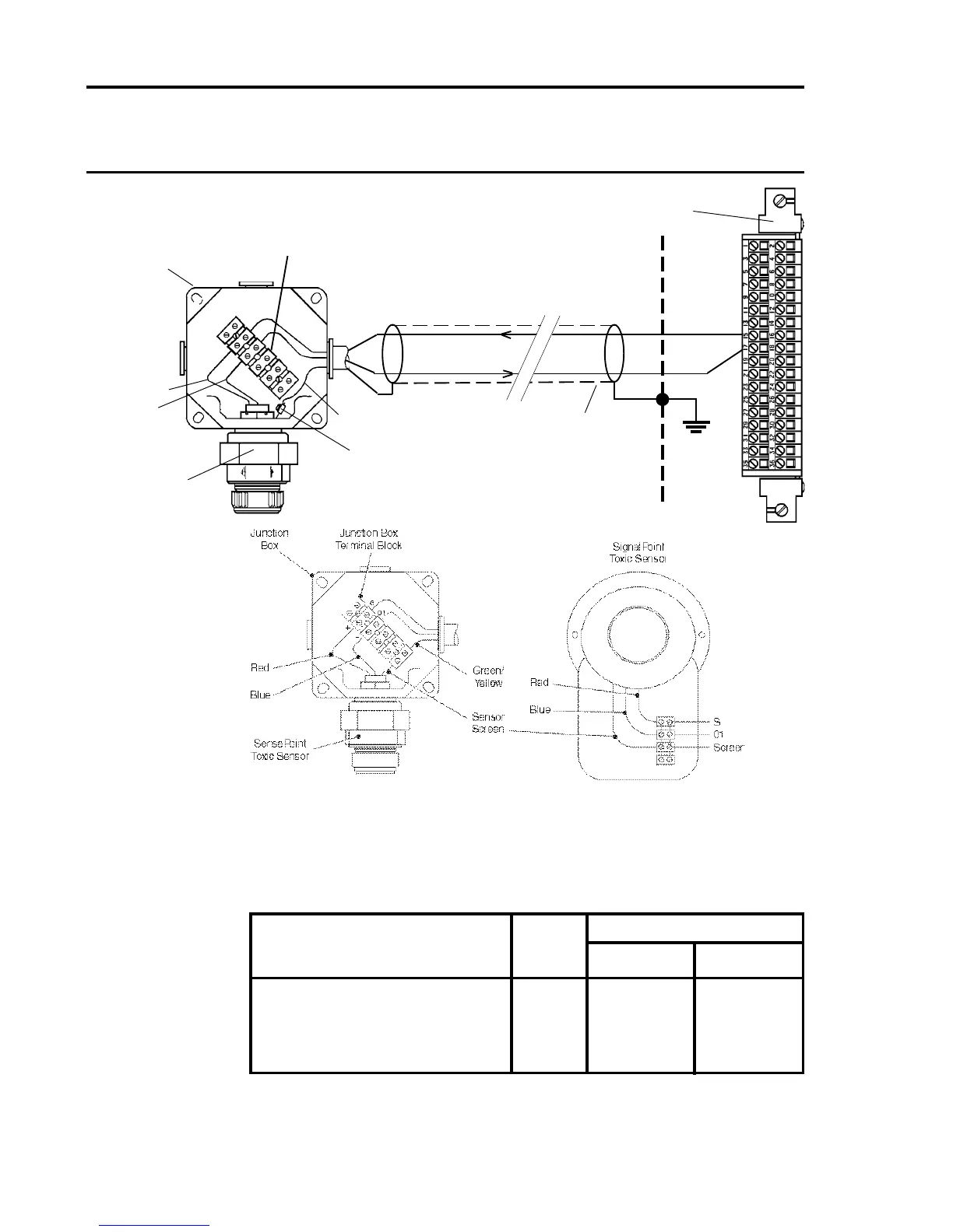
Channel Sensor Connection
S 01
Quad Relay 1 15 17
Interface Connections 2 16 18
3 21 23
4 22 24
Loop Powered Sensor (Measuring Resistance in Supply Return)
Notes: 1. Where a sensor is earthed locally, either to an Earth Stud or through the sensor
casing or mounting, to avoid earth loops the screen sheath of the cable should only
be connected at one end.
2. The above diagram shows the sensor connections for Channel 1. Channels 2, 3 and
4 connections are similar and their pin connection numbers are shown below:
Quad Relay Interface Card
05704-A-0121
S
01
-
+
Arrows Indicate
Direction of Loop
Current Flow
Screened Cable
Earth Terminal
811, 911 ECC,
S2000 Toxic
Sensor
15
17
Brown
Blue
Junction Box
Terminal Block
Junction
Box
Green/Yellow
Cabinet
Protective
Earth
S
01

 Loading...


