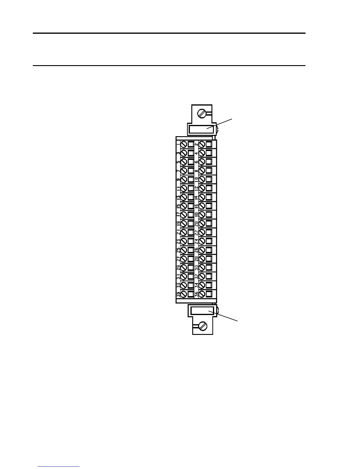
5.2.2 Quad Relay Card Rear Access Connections
RL1-NC (Master Fault) 1 2 RL1-NO (Master Fault)
1. NC = Normally Closed. NO = Normally Open. COM = Common.
2. Relay contact conditions refer to the no power state of the relay.
3. The functions shown for terminals 1 to 12 are the default functions for
relays RL1 to RL4 only. For other congurations - refer to the conguration
printout.
RL1-COM (Master Fault) 3 4 RL2-COM (Master A1)
RL2-NC (Master A1) 5 6 RL2-NO (Master A1)
RL3-NC (Master A2) 7 8 RL3-NO (Master A2)
RL3-COM (Master A2) 9 10 RL4-COM (Master A3)
RL4-NC (Master A3) 11 12 RL4-NO (Master A3)
Ground 13 14 Ground
Channel 1 (S) 15 16 Channel 2 (S)
Channel 1 (01) 17 18 Channel 2 (01)
Channel 1 (NS) 19 20 Channel 2 (NS)
Channel 3 (S) 21 22 Channel 4 (S)
Channel 3 (01) 23 24 Channel 4 (01)
Channel 3 (NS) 25 26 Channel 4 (NS)
Analogue 24V 27 28 Analogue 0V
Analogue CH1 29 30 Analogue CH2
Analogue CH3 31 32 Analogue CH4
Remote Reset 33 34 Remote Inhibit
+24V Input 35 36 0V Input
Slot Location Label
Label for
User Terminal
Reference

 Loading...


