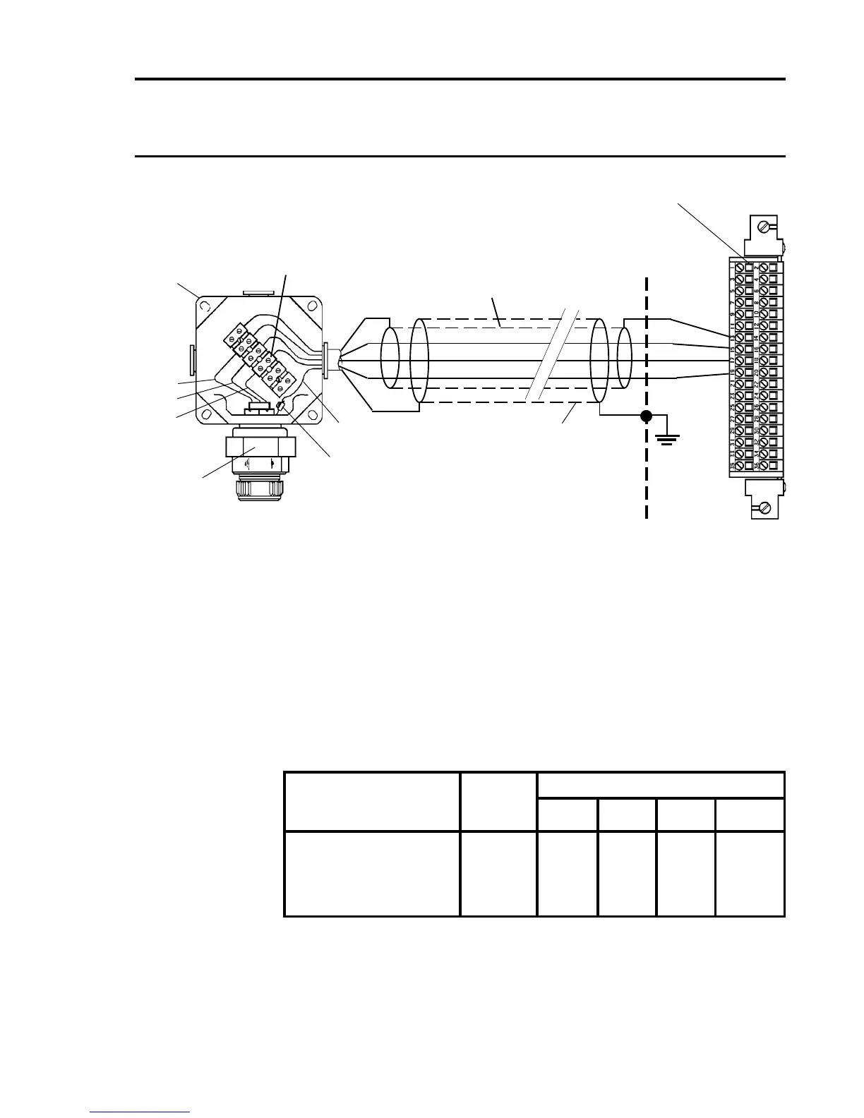
Notes: 1. Where a sensor is earthed locally, either to an Earth Stud or
through the sensor casing or mounting, to avoid earth loops
the screen sheath of the cable should only be connected at
one end.
2. The above diagram shows the sensor connections for Channel
1. Channels 2, 3 and 4 connections are similar and their pin
connection numbers are shown below:
Channel Sensor Connection
S 01 NS Ground
Quad Relay 1 15 17 19 13
Interface Connections 2 16 18 20 14
3 21 23 25 13
4 22 24 26 14
Combustible Sensor, Junction Box and Terminal Block
Connections
NS
Brown
White
Blue
GND
S
01
NS
Junction Box
Terminal
Block
Junction
Box
Quad Relay Interface Card
05704-A-0121
Screened/Armoured
Cable
Earth Terminal
780 Series
910 704/705
980 Sensors
Cabinet
Protective
Earth
Separate Screen Sheath
(If Fitted)
13
15
17
19
S
01
Green/Yellow

 Loading...


