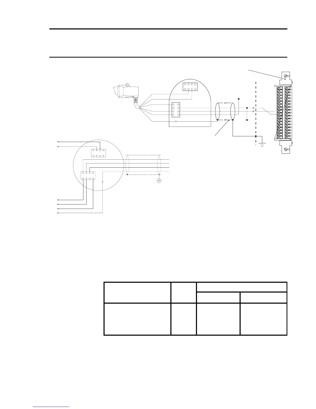
Notes: 1. Where a sensor is earthed locally, either to an Earth Stud or
through the sensor casing or mounting, to avoid earth loops
the screen sheath of the cable should only be connected at
one end.
2. The above diagram shows the sensor connections for Channel
1. Channels 2, 3 and 4 connections are similar and their pin
connection numbers are shown below:
Channel Sensor Connection
01 NS
Quad Relay 1 17 19
Interface Connections 2 18 20
3 23 25
4 24 26
Three Wire Control Card Current Sink, Transmitter Current
Source Connection for Searchline Excel
(Signal Returned to 0V)
4
4
1
1
GND
ORANGE A
+24V DC Supply
BLACK 0V
WHITE 4-20mA
BLUE B
0V DC Supply
4-20mA Output
GRN/YEL GND
RED 24V
+24V*
0V*
53
63
33
43
13
23
92
03
72
82
52
62
32
42
12
22
91
02
71
81
51
61
31
41
11
21
9
01
7
8
5
6
3
4
1
2
Quad Relay Interface Card
05704-A-0121
Arrows Indicate
Direction of Loop
Current Flow
Screened Cable
* 24V supply may be obtained from either
the cabinet or a separate field supply
CabinetField Connections
28
19
17
NS
01
Protective
Earth
(Instrument
or Clean
Earth)
Searchline Excel Receiver
Current Source
Connections using a
DVC100 Junction Box
Receiver Connections
1
4
TB2
TB1
4
1
Earth
Te rminal
Earth
Instrument Earth
Cable
Shield
ORANGE A
0V DC Supply Rx (0V)
IS EARTH IS EARTH
BLACK 0V
WHITE 4-20mA
RED +24V
BLUE B
4-20mA Output Rx (SIG)
GRN/YEL GND
+24V DC Supply Rx (+24V)
Control Cabinet
Connections
Connections using a
DX100 Junction Box

 Loading...


