IFP-300 Series Manual — P/N LS10145-001SK-E:C 4/6/2022 131
Releasing Operations System Operation
9.6.1 Single Interlock Zone Releasing
A single interlock zone utilizes a minimum of two addressable detectors and a designated manual release switch. Only addressable detectors
can be used. No conventional detectors can be used.
Conditions Required for an Interlock Release Alert Output Activation
If any single addressable detector is activated, the “Interlock Release Alert” output will activate. This alerts the user that the initial stages
required for a release condition are present. (Refer to Table 9.5).
Conditions Required for a Detector Alarm and Interlock Release Alarm Output Activation
If two or more addressable detectors, or a manual release switch activate, the “Detector Alarm” and “Interlock Release Alarm” outputs will
activate. (Refer to Table 9.5 below.)
9.6.2 Double Interlock Zone Releasing
A Double Interlock Zone uses a minimum of two addressable detectors, a designated manual release switch, and an interlock switch input.
An interlock switch is typically a dry-contact pressure switch and will be referred to as an interlock/pressure switch in this document. Only
addressable detectors can be used. No conventional detectors can be used.
Conditions Required for an Interlock Release Alert Output Activation
If any single addressable detector is activated, the “Interlock Release Alert” output will activate. This alerts the user that the initial stages
required for a release condition are present. (Refer to Table 9.6.)
Conditions Required for a Detector Alarm Output Activation
If two addressable detectors, a manual release switch is activated, or an interlock switch is active, the “Interlock Release Alert” and “Detec-
tor Alarm” outputs will activate.
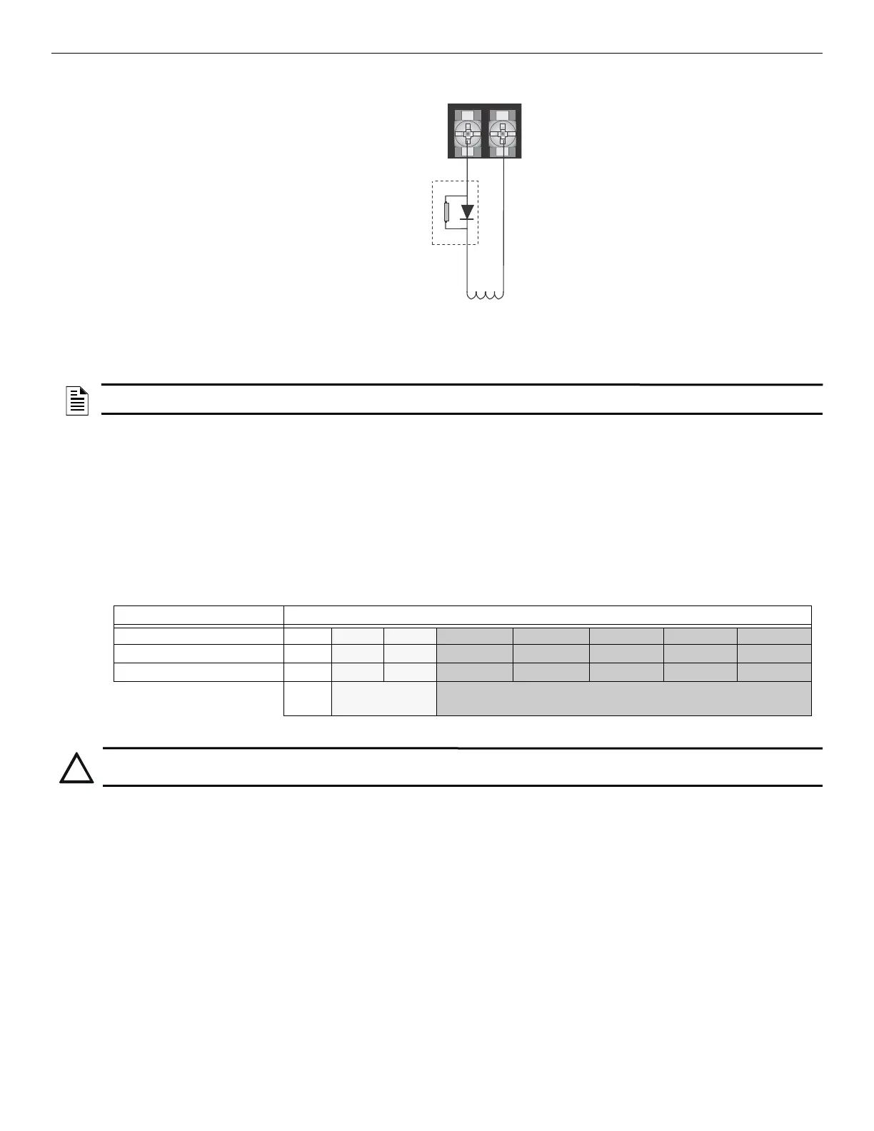
Either NAC circuit
can be used.
UL-listed solenoid
supervisory module-
must be located at the
solenoid.
releasing solenoid
Use 1 solenoid per
circuit.
red
black
Figure 9.6 Wiring Configuration for Solenoid
NOTE: For releasing operations, a manual releasing disconnect switch is required per UL 864. Refer to the MRD-1 Series Document for
installation instructions.
Inputs
Output Results
1st Addressable Detector
X X X X
2nd Addressable Detector
X X X X
Manual Release Station
X X X X
Normal
Interlock Release
Alert
Interlock Release Alarm and Detector Alarm
Table 9.5 Single Interlock Zone Operation
CAUTION: DETECTOR SPACING
DETECTORS MUST BE INSTALLED AT 0.7 TIMES THE LINEAR SPACING AS DESCRIBED IN NFPA 72

 Loading...


