52 IFP-300 Series Manual — P/N LS10145-001SK-E:C 4/6/2022
Control Panel Installation Configuring SBUS Modules
4.14.2 5865 Mounting
Mount the 5865-4 to a standard 4-gang electrical box. Mount the 5865-3 to a standard 3-gang electrical box. In Figure 4.39, the 5865-4
attached to a 4-gang box is used as an example.
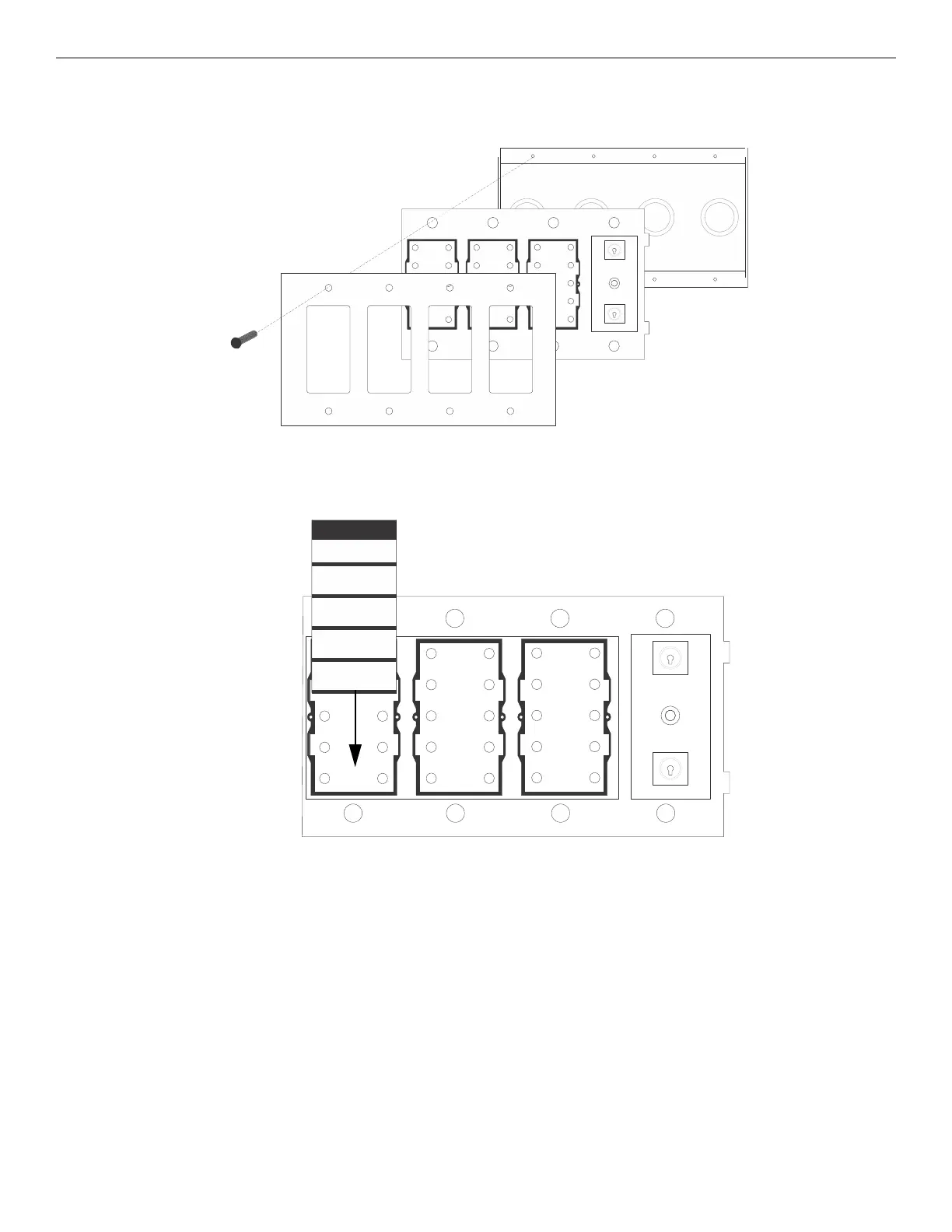
The 5865 ships with a set of zone description labels that can be inserted into the 5865 board assembly. These labels can be used in a type-
writer or can be written on by hand. Slide the labels under the plexiglass as shown in Figure 4.40. The LEDs will show through the label
when illuminated.
4.15 Configuring SBUS Modules
This section describes how to configure any system hardware modules that have been added to the system.
4.15.1 Assigning SBUS Module IDs
When installing a hardware module (see Table 4.2 for list of compatible SBUS devices), you must use the DIP switches on the module to
assign an ID# to the module. Figure 4.41 shows all possible DIP switch positions and their correlation to a numerical ID. Address 0 is an
invalid address and cannot be used. For example, to select ID 2, place DIP switch 2 in the up position.
Attach the 5865 to a
standard 3- or 4-gang
electrical box.
The 5865 is mounted to a
plexiglass plate at the factory.
cover plate
Figure 4.39 5865 Mounting Example
RESET
TOP
Zone 1
1st Flr South
Zone 2
1st Flr West
Zone 3
2nd Flr West
Zone 4
2nd Flr East
Zone 5
3rd Floor
Figure 4.40 Inserting Zone Description Labels

 Loading...


