IFP-300 Series Manual — P/N LS10145-001SK-E:C 4/6/2022 35
Wiring Specifications Control Panel Installation
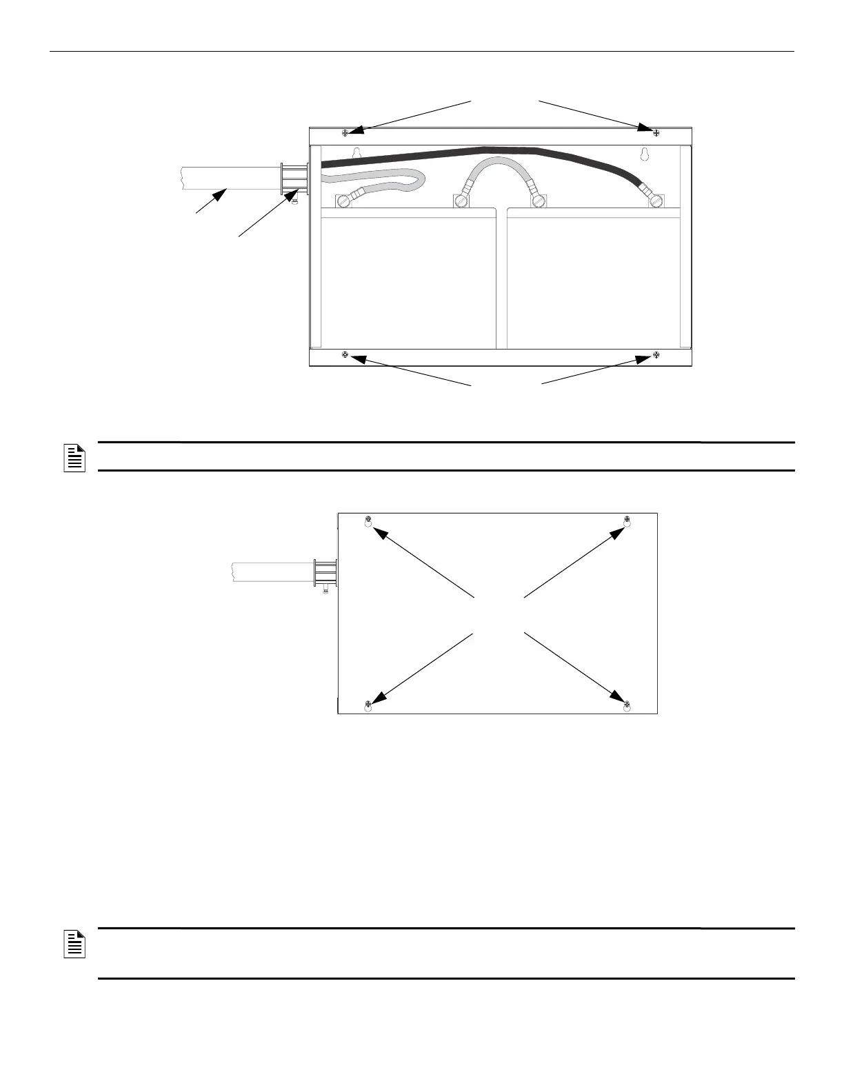
5. Insert the RBB cover screws into the cover mounting holes and screw down most of the way. Do not tighten.
6. Align the cover plate mounting keyhole over the cover mounting screws.
7. Slide the cover into place and tighten the cover mounting screws.
4.6 Wiring Specifications
4.6.1 Length Limitations
This section contains information on calculating SBUS wire distances and the types of wiring configurations (Class A and B).
4.6.2 Calculating Wiring Distance for SBUS Modules
The following instructions will guide you in determining the type of wire and the maximum wiring distance that can be used with SBUS
accessory modules.
To calculate the wire gauge that must be used to connect SBUS modules to the panel, it is necessary to calculate the total worst case current
draw for all modules on a single 4-conductor bus. The total worst case current draw is calculated by adding the individual worst case currents
for each module. The individual worst case values are shown in the table below.
RBB cabinet
cover screws
RBB cabinet
cover screws
conduit coupler
conduit
Figure 4.9 Battery Connections in the RBB Cabinet
NOTE: Figure 4.3 is an example of how the wire connections can be routed. However, any other cabinet knock-outs (on either the main control
panel or the RBB cabinet), that are not previously being used may be utilized to connect conduit between the two cabinets.
Figure 4.10 Cover Plate Mounting Keyholes and Cover Mounting Screws Alignment
cabinet
mounting
holes
NOTE: Total worst case current draw on a single SBUS cannot exceed 1 amp. If a large number of accessory modules are required and the
worst case current draw will exceed the 1 amp limit, then the current draw must be distributed using RPS-1000 Power Expanders. Each RPS-
1000 Power Expander provides an additional SBUS, with an additional 1 amp of SBUS current. Wiring distance calculations are done separately
for each RPS-1000, and separately for the panel itself.

 Loading...


