IFP-300 Series Manual — P/N LS10145-001SK-E:C 4/6/2022 79
Mapping Overview Programming Overview
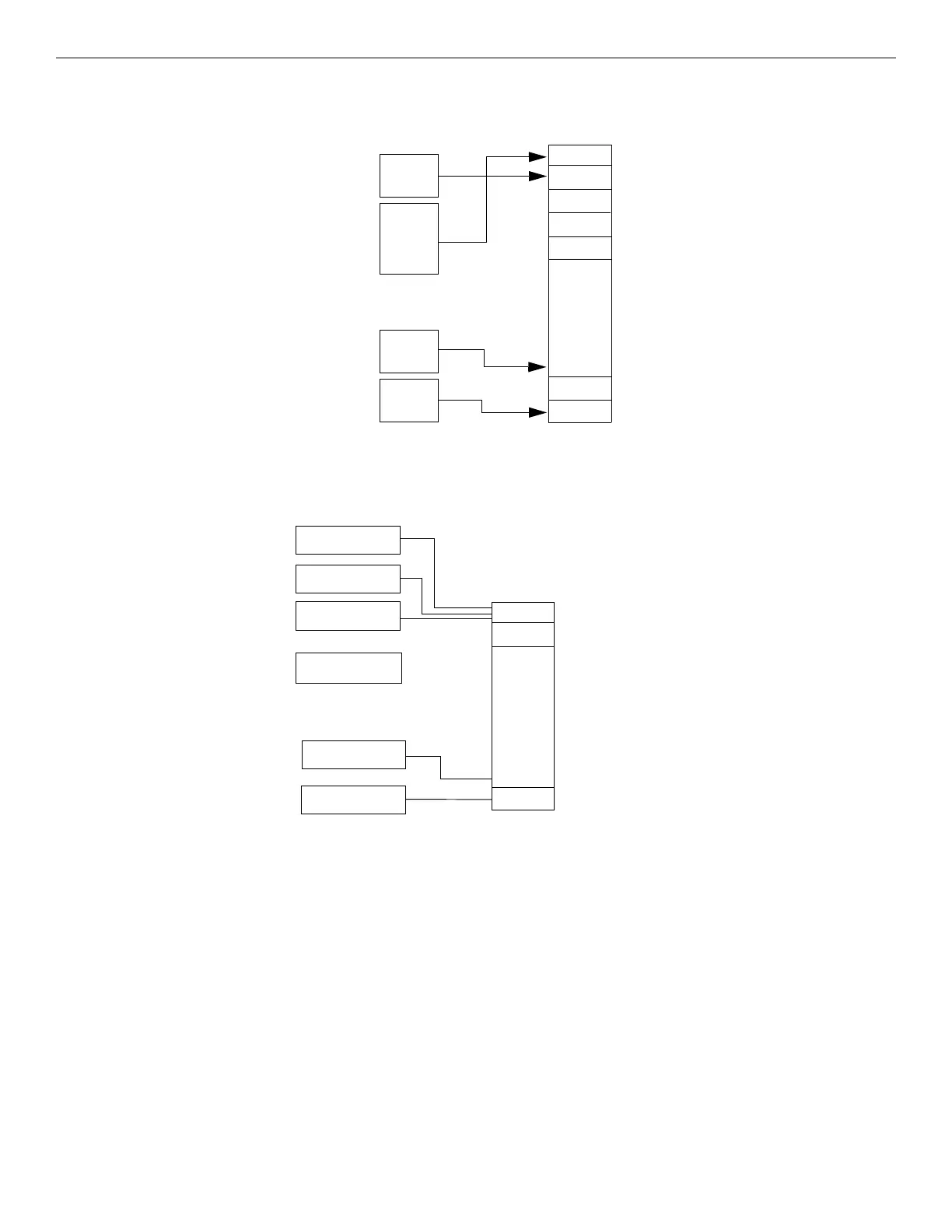
7.2.1 Input Point Mapping
Input points are assigned to input zones. Any input point can be assigned to any input zone. (Input points can be assigned to one zone only.
An input point can be designated as “Unused,” which means it has not been assigned to a zone.)
7.2.2 Output Circuit Mapping
Figure 7.3 is a simple example showing how to assign notification and relay output circuits to groups. For an example of a simple floor
above/floor below application, see Figure 7.5.
point 1
point 2
point 3
point 4
point 5
point 6
point 7
point 8
point 295
point 296
point 297
point 298
point 299
point 300
point 4
point 5
point 6
point 7
point 8
through
zone 1
zone 2
zone 3
zone 4
zone 5
zone 6
through
zone 248
zone 249
zone 250
Figure 7.2 Input Point Assignment Example
output circuit 3
NAC circuit
output circuit 4
aux power output
Aux power outputs are not
mapped to output groups.
group 1
group 2
through
group 249
group 250
output circuit 5
Relay 1
output circuit 6
Relay 2
In this example, all NAC outputs
are assigned to group 1.
JumpStart creates group 249 and
group 250 for Relay 1 and Relay 2.
output circuit 1
NAC circuit
output circuit 2
NAC circuit
Figure 7.3 Assigning Output Circuits to Groups (Example)

 Loading...


