130 IFP-300 Series Manual — P/N LS10145-001SK-E:C 4/6/2022
System Operation Releasing Operations
9.5.1 Multi-Site Annunciator and Multi-Site User Access
Multi-site annunciators are unique as they can display the status and event history of all sites they are assigned to. These displays can be
especially useful in guard shacks or security centers. A multi-site display is indicated by the words “Multi-Site Display” at the top of the Idle
screen.
• The ACK, DRILL, RESET and F-Macro keys are disabled until a multi-site user access code has been entered and a specific site has
been selected.
• Multi-site Annunciator silencing rules:
– If any of the assigned sites are silenced, the Silenced LED will be lit.
– Silence key will only silence the sound from the multi-site annunciator on which the silence key was pressed. This is called being
Locally Silenced. If Locally Silenced is enabled on a multi-site annunciator, it will be indicated by a blinking Silenced LED.
– If any new troubles, supervisory, pre-alarms, or alarms are triggered in any assigned sites, locally silenced annunciators will resound.
– If a multi-site annunciator is locally silenced for 4 or 24 hours, depending on user selection, the locally silenced annunciators will
resound.
• The IFP-300 Menu System is disabled on a multi-site annunciator. Pressing the Right or Enter keys will bring you straight into event
history for assigned sites. To get into the menu system, a multi-site user password must be entered and then a site must be selected from
the site selection menu. Once this is done you will have access to the Idle screen of that site and the annunciator will temporarily act like
a single site annunciator.
• A multi-site annunciator will sound the highest priority tone from the sites it is assigned to.
9.6 Releasing Operations
The control panel supports two types of releasing: Double Interlock Zone and Single Interlock Zone.
• The Double Interlock Zone operation requires an interlock switch input in the system.
• The Single Interlock Zone does not. An interlock switch is typically a dry-contact pressure switch.
When Single or Double Interlock Zone releasing is selected using HFSS, the software suite will automatically default the following system
parameters:
• Output Group 2 is created. Output Group 2 will be defaulted as a “Detector Alarm” output group for all releasing zones. NAC [98:001]
is assigned to Output Group 2.
• Output Group 3 is created. Output Group 3 will be defaulted as a “Interlock Release Alert” output group for all releasing zones. NAC
[98:002] is assigned to Output Group 3.
• Output Group 4 is created. Output Group 4 will be defaulted as “Interlock Release Alarm” output group for all releasing zones. NAC
circuit [98:003] is assigned to Output Group 4.
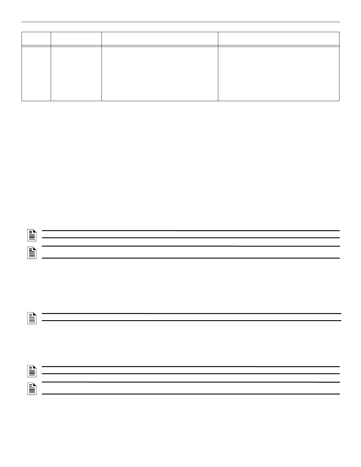
Silenced An alarm or trouble
condition has been
silenced but still
exists. To silence
alarms and troubles,
press SILENCE
followed by the
Installer or User Code,
if necessary.
The SYSTEM SILENCE LED is on. The SYSTEM
TROUBLE, SUPERVISORY, and/or GENERAL
ALARM LED (depending on condition) is on. The
annunciator (and any notification devices attached to
the system) will be silenced.
Press down arrow to view the location of the alarm,
supervisory, or trouble. When the condition no longer
exists, the SYSTEM SILENCED and SYSTEM
TROUBLE LED, SUPERVISORY and/or GENERAL
ALARM LEDs turn off.
Operating
Mode
Occurs When System Behavior In This Mode You Can
Table 9.4 Panel Operating Modes (Continued)
NOTE: A multi-site display is created in Module programming in the edit properties menu for an annunciator. See Section 8.2.1.
NOTE: An annunciator cannot be programmed as a multi-site display when it is associated with an ECS-VCM, ECS-NVCM, or ECS-RVM in an
ECS system.
NOTE: The defaults created can be modified through programming if desired.
NOTE: The Installer must define which input points will be used for detectors, manual release switches, or interlock/pressure switches.
NOTE: For manual release operations, FM approved/ UL listed releasing manual station must be used. Refer to the Device Compatibility
Document for approved releasing devices.

 Loading...


