82 IFP-300 Series Manual — P/N LS10145-001SK-E:C 4/6/2022
Programming Overview Programming Using the HFSS Software Suite
7.2.4 Mapping LED Points
Figure 7.7 is a simple example showing how LED points are mapped to zones and output groups. Typically you would create two output
groups for each zone, one for alarms and one for troubles. (LED points are available when Models 5865-3/4 and/or 5880 are used with the
system.)
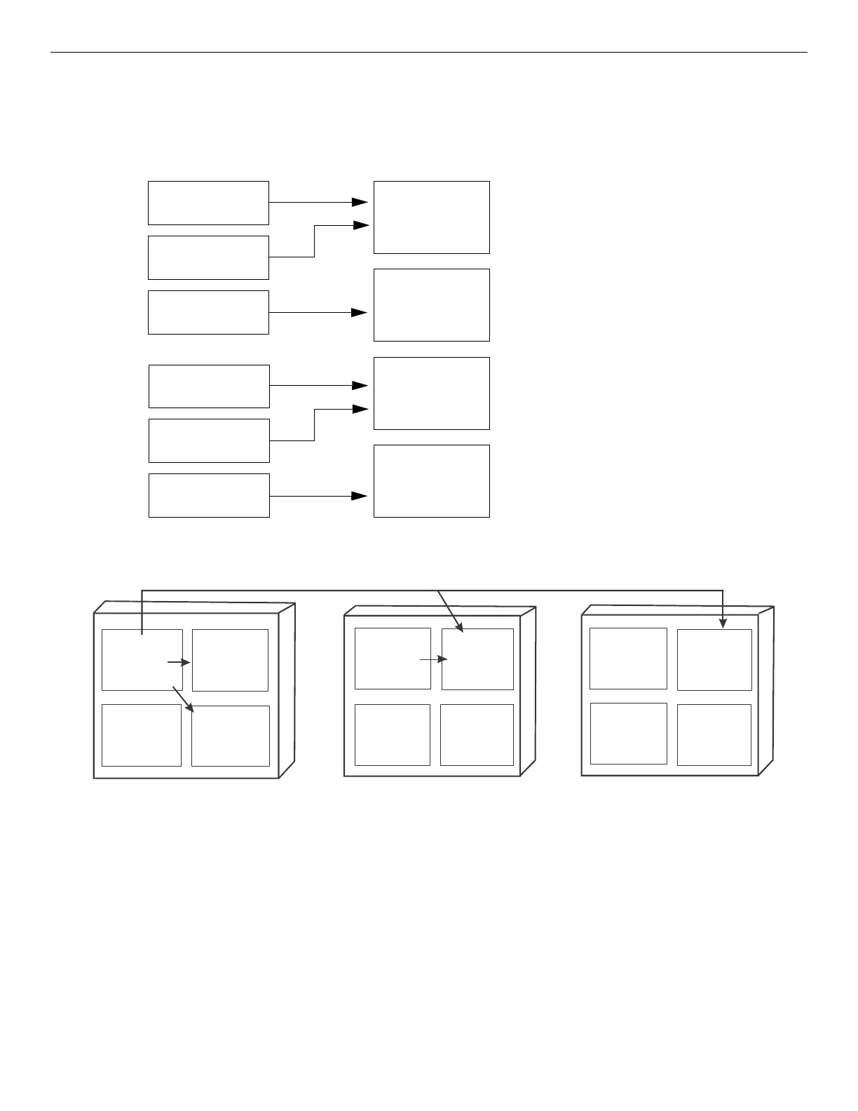
7.2.5 Mapping LED Points for a Networked System
7.3 Programming Using the HFSS Software Suite
You can use the HFSS Honeywell Fire Software Suite to program the control panel on-site (personnel will need to be on-site during the
upload or download process). HFSS is a software package that lets you easily program the control panel using a Windows-based computer.
HFSS is needed for mapping. When using HFSS, you can set up the programming options for the panel, save the options in a file, then down-
load the file to the panel. You can connect to the control panel directly using the onboard USB or Ethernet. Updates are available at www.far-
enhyt.com
Zone 1
manual pull alarm
Zone 1
detector alarm
Zone 1
trouble
Output group 1
red LED 1
alarm outputs
(horns, strobes, etc.)
An alarm in Zone1 will activate red
LED1 and any other required outputs.
Output group 2
yellow LED 2
maintenance room
sounder
A trouble in Zone1 will activate yellow
LED2 plus any other needed outputs.
(In this example, it activates a sounder in
the maintenance room.)
Output group 3
red LED 3
alarm outputs
(horns, strobes, etc.)
An alarm in Zone2 will activate red
LED3 and any other required outputs.
Output group 2
yellow LED4
A trouble in Zone2 will activate yellow LED4.
Zone 2
manual pull alarm
Zone 2
detector alarm
Zone 2
trouble
Mapping LEDs to Zones and Output Groups
Figure 7.7 Example of LED Points Mapped to Output Groups (applies to Models 5865-3/4 and 5880)
An alarm in Zone 1, Panel 1 could activate the red LED in Output Group of Panel 1, 2, and 8.
Panel 1 Zone 1
Manual Pull
Alarm
Output Group 1
red LED1 alarm
output (horn,
strobes, etc.)
Panel 1 Zone 1
Detector Alarm
Output
Group 2
Output
Group 2
Output
Group 2
Output
Group 1
Red LED
Panel 2
Zone 1
Panel 2
Zone 2
Panel 8
Zone 1
Panel 8
Zone 2
Output
Group 1
Red LED
Panel 1
Panel 2
Panel 3
Note: If the panels are not in the same site, the mapping must be set to non-latching to disable the LED when the Trouble/Alarm is cleared.
Figure 7.8 Example of Expanding Mapping of LED Points Across Panels

 Loading...


