IFP-300 Series Manual — P/N LS10145-001SK-E:C 4/6/2022 47
5824 Serial/Parallel Printer Interface Module Installation Control Panel Installation
You are now ready to connect SLC devices to the 6815. Figure 4.29 is a drawing of the 6815 board, showing the location of terminals and
DIP switches.
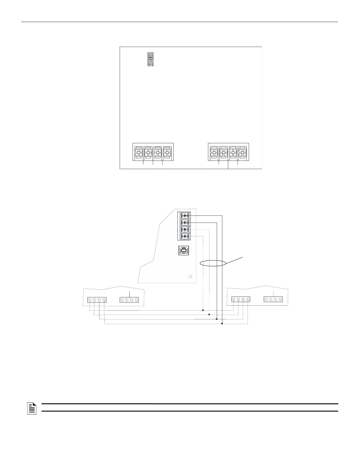
4.11.1 6815 Connection to the Panel
Connect the 6815 to the control panel as shown in Figure 4.30. After the 6815 is connected to the panel, it must be added to the system. This
programming steps are described in Section 8.2.2.
4.12 5824 Serial/Parallel Printer Interface Module Installation
The 5824 serial/parallel printer interface module allows you to connect a printer to the panel, so you can print a real-time log of system
events. Instructions for installing the 5824 appear below.
The 5824 and the printer connected to the 5824 Parallel port is ancillary, the serial port can be used for primary fire signaling. The printer
must be a UL 864 listed printer.
5824 installation involves the following steps.
1. Ensure the power is off at the panel.
2. Connect the 5824 to the panel as shown in Figure 4.31.
3. Use the DIP switches on the back of the board to assign an ID# to the 5824 (see Section 4.15.1).
4. Configure the 5824 device through programming. See Section 4.12.1.
SBUS
–
+
A
B
SLC OUT
S+ SC- S+SC-
SLC IN
ON
12345
6
DIP switches for
setting IDs
to panel SBUS to SLC loop
Figure 4.29 6815 Board
Out
SBUS
SLC In
SC- SC-
S+ S+
-
+
A
B
SLC Out
SBUS
SLC In
supervised,
power-limited,
Class B
IFP-300
6815 6815
Figure 4.30 6815 Connection to IFP-300
NOTE: There is a maximum of four 5824 modules per panel.

 Loading...


