IFP-300 Series Manual — P/N LS10145-001SK-E:C 4/6/2022 55
Notification Appliance/Auxiliary Power Circuits Control Panel Installation
2. Configure the circuit for Class A in programming (see Section 8.5).
Maximum voltage drop is 3V per Class A circuit.
4.17.2 Auxiliary Power Installation
NAC Circuits 1-4 on the control panel can be used as auxiliary power circuits. The wiring class of the external power source must match the
wiring class of the device being powered. The four types of auxiliary power available are:
•Door Holder
• Constant
• Resettable Power
• Sounder Sync Power
Auxiliary power circuits are power-limited. Each circuit can source up to 3A (total current for all NAC circuits must not exceed 6A).
To install an auxiliary power circuit:
1. Wire the NAC circuit(s) that will be used for auxiliary power.
2. Configure the auxiliary power output through programming (see section Section 8.5).
Door Holder Power
Door holder power is intended for fire door applications. When there are no alarms in the system and the panel has AC power, door holder
circuits have 24-volt power present at their terminals. Any alarm will cause power to disconnect. Power will be re-applied when the system
is reset. If AC power is off for more than 15 seconds, the auxiliary door holder power will be disconnected to conserve the battery backup.
When AC power is restored, power is immediately restored to the door holder circuits.
Constant Power
Use constant power for applications that require a constant auxiliary power source. Power is always present at constant circuits.
Resettable Power
Resettable power is typically used to power beam detectors, flame detectors and conventional 4-wire smoke detectors. For circuits selected
as Resettable, 24-volt power is always present at the terminals unless a system reset occurs. If a system reset occurs, power is disconnected
from the terminals for 30 seconds, then re-applied.
Sounder Sync Power
Sounder Sync Power continuously outputs the System Sensor synchronization pattern and is intended for use with B200S Intelligent sounder
bases.
Current Maximum Impedance
1.0A 3Ω
1.5A 2Ω
2.0A 1.5Ω
2.5A 1.2Ω
3.0A 1.0Ω
Table 4.8 Maximum Impedance Class A
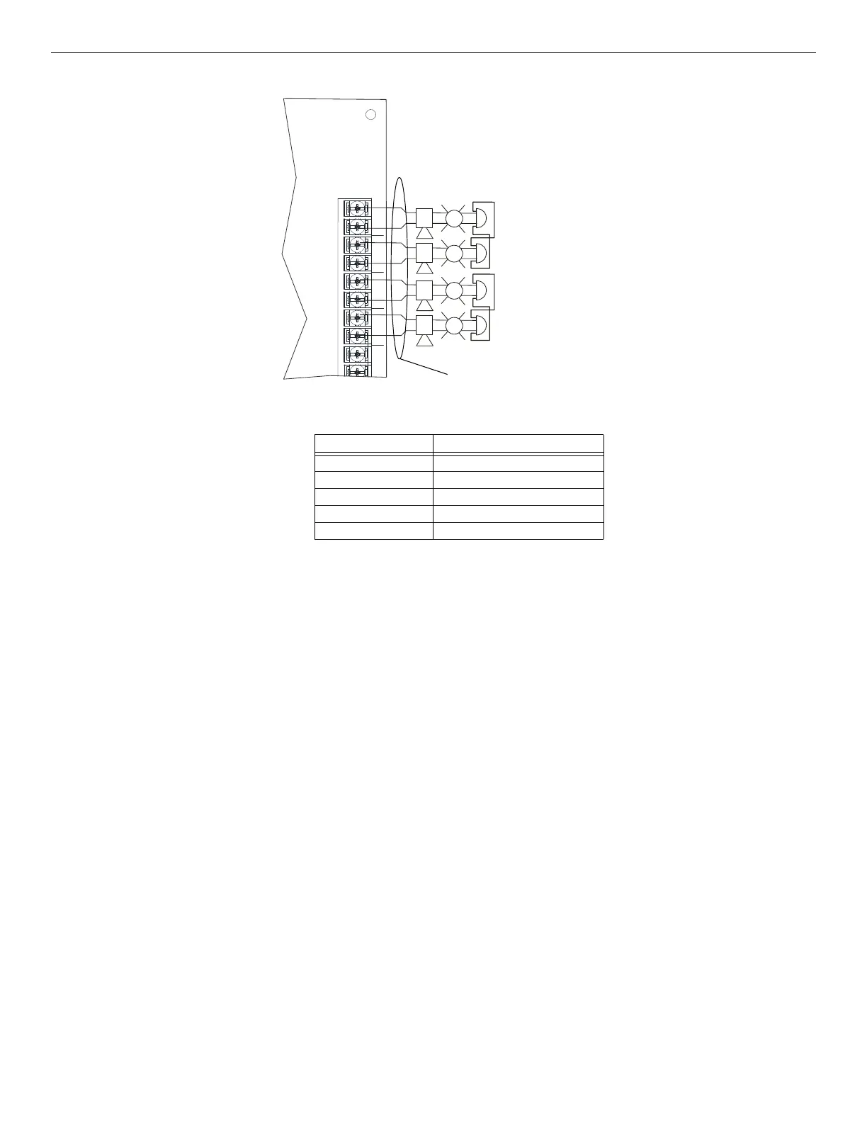
LAY2
C NO
NAC1 NAC2 NAC3 NAC4
+ - + - + - + -
+
+
+
+
+
+
+
+
+
+
+
+
Max. Impedance: 1.5Ω
All Circuits are Synchronized (Regulated).
Rated @ 27.4 VDC @ 3A Max.
Figure 4.44 Class A Notification Appliance Circuit Configuration
supervised, power-limited
Alarm Polarity Shown

 Loading...


