IFP-300 Series Manual — P/N LS10145-001SK-E:C 4/6/2022 41
RA-1000 Remote Annunciator Installation Control Panel Installation
RA-1000 installation involves the following steps:
1. Ensure the power is off at the panel.
2. Mount the RA-1000 in the desired location (see Section 4.8.1).
3. Connect the RA-1000 to the panel (see Figure 4.11).
4. Use the DIP switches on the back of the RA-1000 to assign an ID# to the annunciator (see Section 4.15.1).
5. The new RA-1000 module must be added to the system through programming. JumpStart will add the module automatically (see
Section 8.1). You can also add it manually (see Section 8.2.2). Select a name, if desired.
4.8.1 Mounting the RA-1000
This section of the manual describes mounting the remote annunciator. The annunciator can be flush- or surface-mounted. Figure 4.18 shows
the parts of the annunciator. Instructions for disassembling and mounting appear on the following pages.
The RA-1000 comes from the factory fully assembled. You must disassemble it for mounting. To disassemble the annunciator, use a 5/64 hex
wrench to remove the set screws, located on the bottom of the annunciator bezel. (See Figure 4.19 for location of the set screws.)
Flush Mounting
This section of the manual describes flush mounting. You can flush-mount with or without an electrical box.
Flush Mounting with an Electrical Box
The RA-1000 annunciator can be used with the following types of electrical boxes: 4S, single-gang, and double-gang.
If an electrical box is used, the box must be 1-3/8” back from the face of the wall to accommodate the annunciator. Studs used with an elec-
trical box must be 2x4” (or larger).
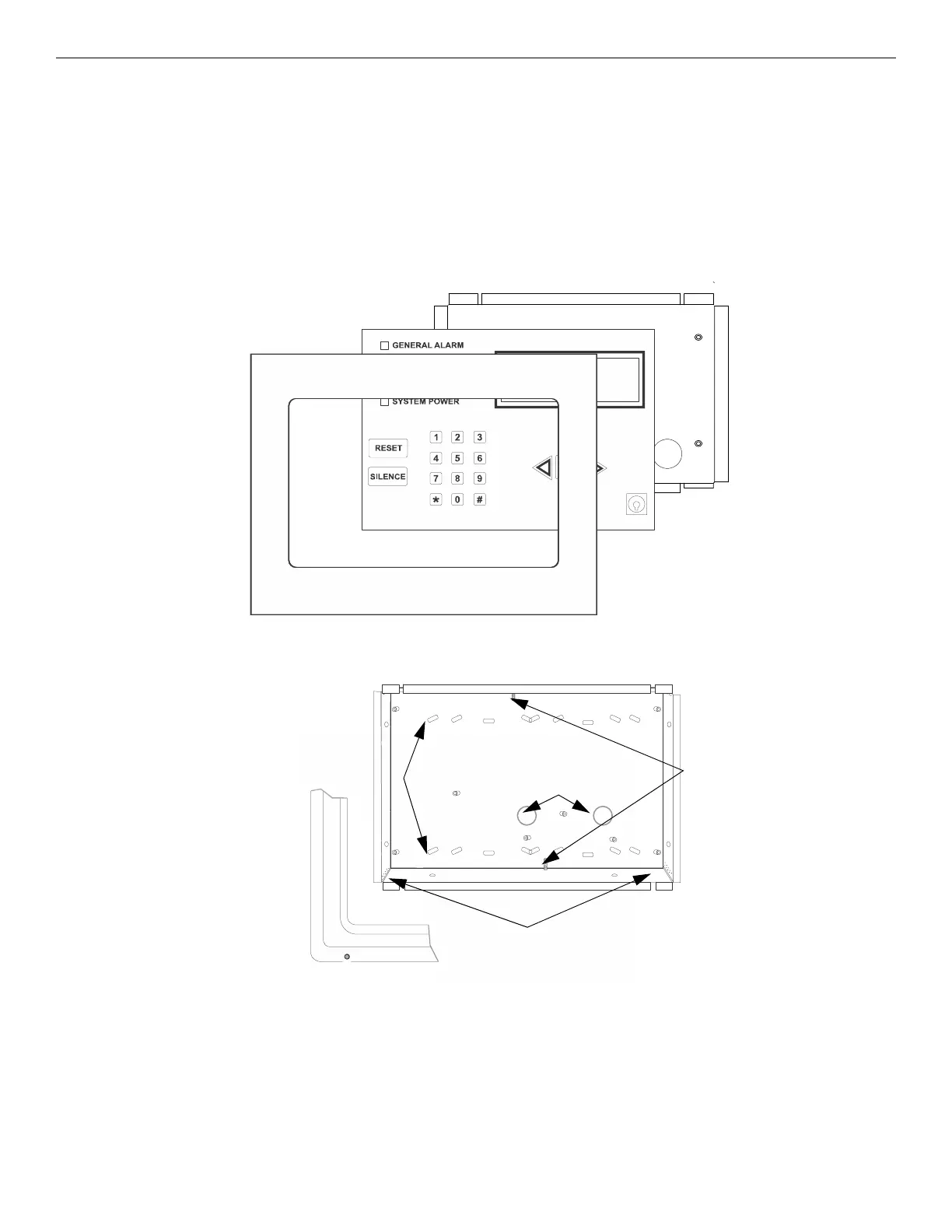
Figure 4.18 Annunciator Parts
knockouts
screws for placement
of mounting wires
Set Screw
holes for inserting wires
for flush-mounting
(located in all corners)
surface mounting holes
knockouts
Figure 4.19 Annunciator Backbox and Bezel Details

 Loading...


