IFP-300 Series Manual — P/N LS10145-001SK-E:C 4/6/2022 49
5880 LED I/O Module Control Panel Installation
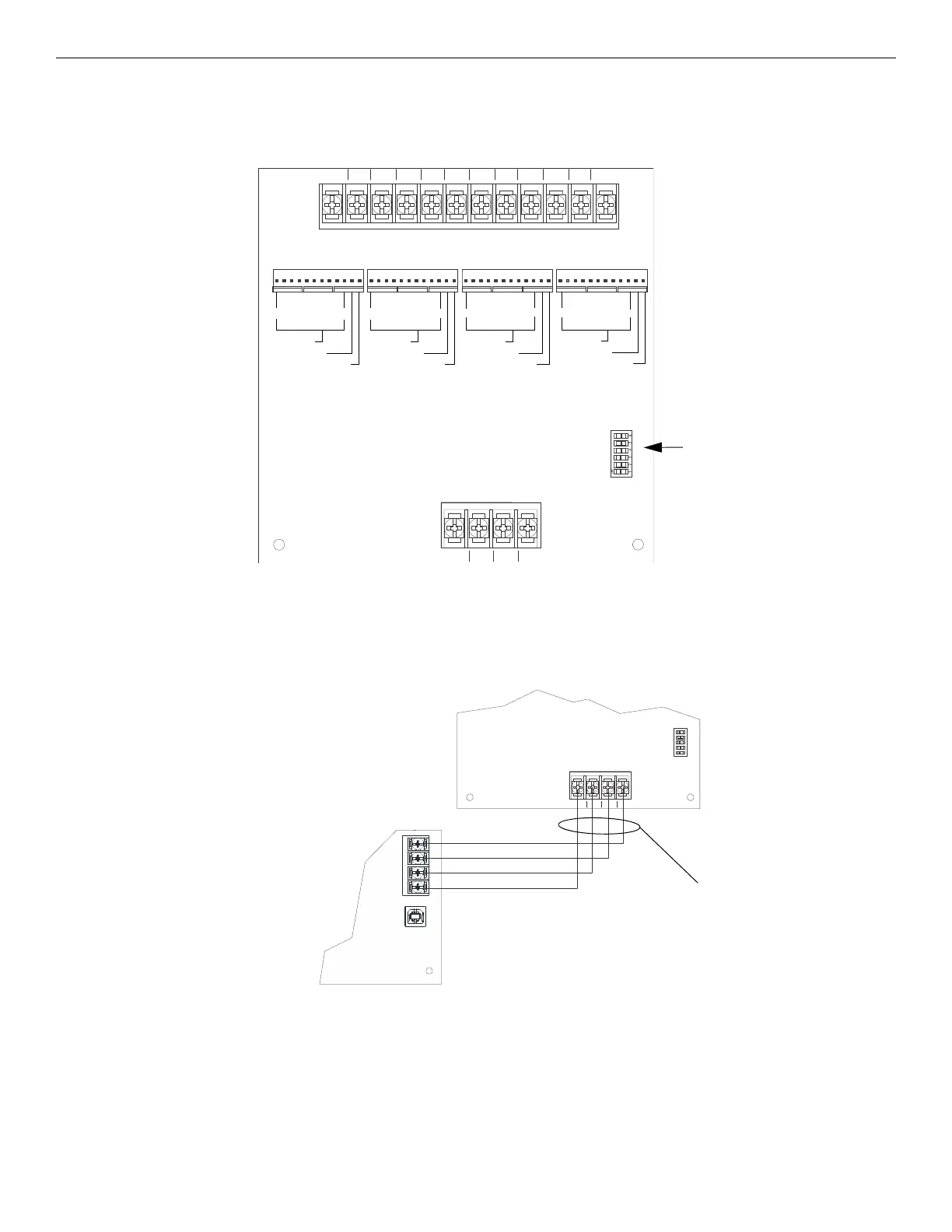
4.13.1 5880 Board Layout
Figure 4.33 is a picture of the 5880 board showing locations of screw terminals for connection to the panel and contact monitor wiring, pin
connectors for connecting LEDs, and a DIP switch for selecting an SBUS ID number.
4.13.2 5880 Connection to Panel
The 5880 connects to the panel via the SBUS. Make connections as shown below. After the 5880 is connected to the panel, it must be added
to the system. This programming step is described in Section 8.
4.13.3 LED Wiring
There are four 12-pin connectors on the 5880 board for connecting LEDs. Each LED gets its power from Pin 11. Internal resistors are sized
so that there is approximately 10 mA of current for each LED, no series resistors are required. LED outputs can be mapped to output circuits.
See Section 8 for programming details.
Wire the LEDs as shown below.
S-
S+
A
B
IN - 48 C+ IN - 47
IN - 46 C+ IN - 45 IN - 44 C+ IN - 43 IN - 42 C+ IN - 41
P1
P2 P3 P4
LED Out
LED Power
not used
LED Out
LED Power
not used
LED Out
LED Power
not used
LED Out
LED Power
not used
SBUS (ID#) Address
DIP switch
SBUS Connector
Figure 4.33 5880 Board Layout
dry contact inputs- supervised, power-limited
S-
S+
A
B
1
ON
2345
SBUS OUT
- +
A B
supervised,
power-limited,
Class B
5880
FACP
Figure 4.34 5880 Connection to IFP-300

 Loading...


